| d'Armond's Home | |
| Klingon | |
| Cozy Mark IV |
|
| Linguistics | |
| FTS |
Cozy Mark IV : Chapter 05
Fuselage Sides
In this chapter you construct the longerons and fuselage sides.
Pictures and commentary will go here as the work progresses. See also time and expenses related to this chapter.
<- Back to Chapter 4 | Home | To Chapter 6 ->
- Step 1. Cutting the Jigs and Laminating the Top Longerons
- Step 2. Building the Forms for the Fuselage Sides and Preparing the Sides for Contouring
- Step 3. Contouring the Sides
- Step 4. Inside Layup and Installing the Upper Longerons
- Step 5. Installation of Lower Triangular Longerons
- Step 6. Completion of the Fuselage Sides
| Step 1. Cutting the Jigs and Laminating the Top Longerons | |
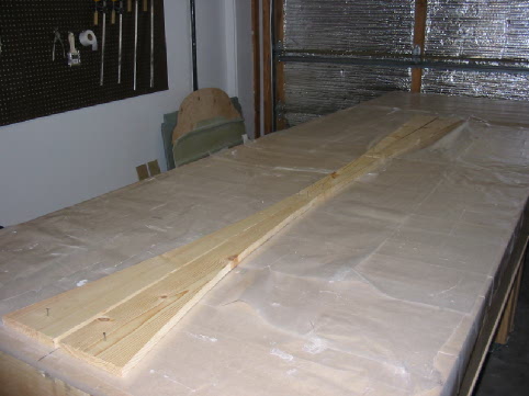
| 9/27/03 Jigs nailed to the table and ready to go. I put down wax paper before nailing the jigs down, seemed to me this would be easier than messing around with this afterwards. |
 |
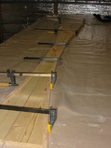
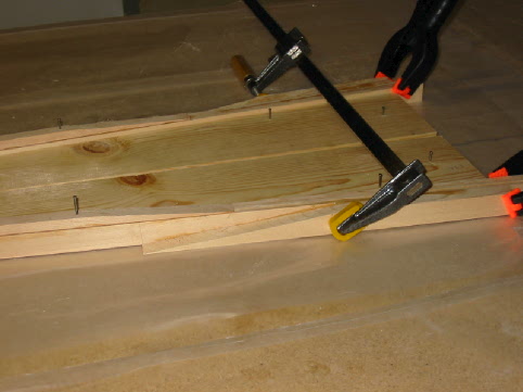
| 9/27/03 The longerons are epoxied together and clamped to the jigs. I had to add more nails! |
 |
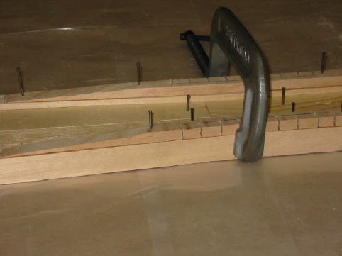
| 9/27/03 Here's a shot of the stiffener nailed in place. |
 |
| 9/27/03 The FJA doublers floxed and nailed in place. |
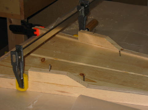 |
| 9/27/03 The FJC doublers floxed and clamped in place. This seemed rather strange to me, but I attached them the way the plans called for, and as near as I can tell from checking out other people's websites as well. If I got this wrong... |
 |
| 9/27/03 The whole assembly is curing. |
 |
| Step 2. Building the Forms for the Fuselage Sides and Preparing the Sides for Contouring | |
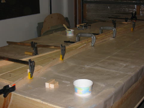
| 9/28/03 The hardboard nailed to the upright jigs. I didn't use bondo, I used angle brackets to fasten the jigs to the table. |
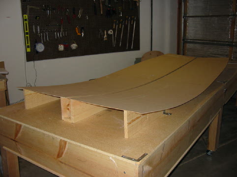 |
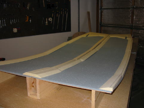
| 9/28/03 The foam for the fuselage sides 5ME'd to the jigs. |
 |
| 9/29/03 The spacers are all cut out and ready for micro. I tried using the miter saw to cut the angles, but I didn't like how it turned out. I ended up using a hack saw blade, and cutting them by hand. Sanding them down with some 120 grit made for a very nice edge, and it was fairly easy to get the pieces to line up nicely. |
 |
| 9/29/03 Close-up of the aft spacer. I really sweated over the electrical conduit. The plans don't tell you how long to make it, or what angle to bevel it at. I followed the discussion in the FAQ, making it 6" from the firewall side, with the bevel to 8". There was also some discussion of whether to cut it at 14.5" from the top, or 14.7". I stuck with the plans dimensions, and put it at 14.5". We'll see if that was a mistake. |
 |
| 9/29/03 All the spacers have been micro'd into place, and nails are holding them to the curves. |
 |
| Step 3. Contouring the Sides | |
| 9/30/03 I used sandpaper stapled to a wood scrap to sand out the depressions for the control sticks. Thanks to a tip from my wife, I used a pen tied to a string, tied to a nail at the other end 4" away, to make a make-shift compass, and trace the outline for the circle. |
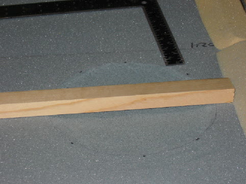 |
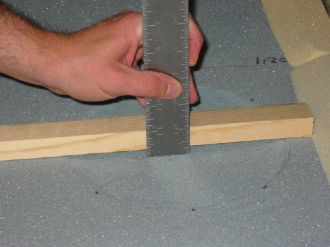
| 9/30/03 I figured out how to tell how deep the depression is. |
 |
| Step 4. Inside Layup and Installing the Upper Longerons | |
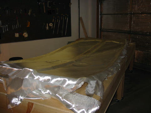
| 9/30/03 This is the 2nd ply of UNI, before applying epoxy. |
 |
| Step 5. Installation of Lower Triangular Longerons | |
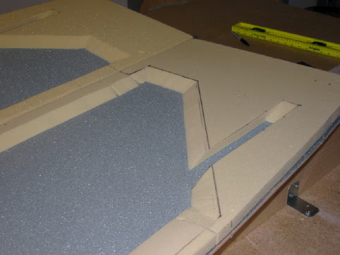
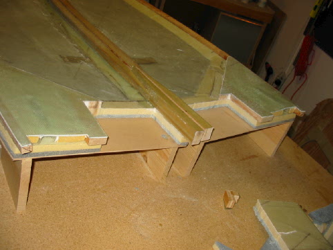
| 6/11/04 Closeup of the main spar cutouts and glassed electrical conduits. |
 |
| Step 6. Completion of the Fuselage Sides | |
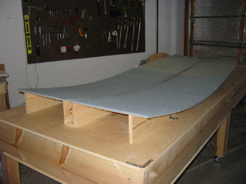
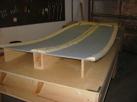
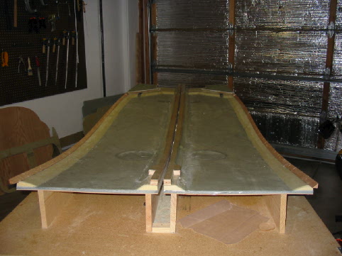
| 6/11/04 Sides are glassed and dry. |
 |
<- Back to Chapter 4 | Home | On to Chapter 6 ->
| Copyright (c) 2003, d'Armond Speers All Rights Reserved |
Last modified: Sunday, February 13, 2005 |