| d'Armond's Home | |
| Klingon | |
| Cozy Mark IV |
|
| Linguistics | |
| FTS |
Cozy Mark IV : Chapter 04
Fuselage Bulkheads
In this chapter you make the 8 fuselage bulkheads.
Pictures and commentary will go here as the work progresses. See also time and expenses related to this chapter.
- Step 1. Front Seatback
- Step 2. Forward Bulkheads
- Step 3. Instrument Panel
- Step 4. Landing Gear Bulkheads
- Step 5. Firewall
| Step 2. Forward Bulkheads | |
| Here's a shot of the F22 bulkhead and doubler, before bonding them together with 5-minute epoxy. I cut these out with a utility knife. It took a very long time, and really wore me out! I still have the instrument panel to cut out, which I also expect to be very hard. | 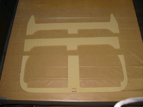 |
| Here's the F28 bulkhead. I decided to cut it out of the large cutouts from F22, which is why it's in 4 pieces. This way, F22 and F28 are cut entirely from two pieces of Last-A-Foam. | 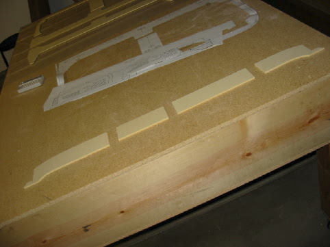 |
| Step 3. Instrument Panel | |
| The instrument panel cutout, before bonding with 5-minute epoxy. I cut this out using a coping saw. It was MUCH easier to cut, but perhaps the lines were a little less straight. Not enough to matter, and my arms couldn't have taken another day of cutting this stuff with a utility knife. | 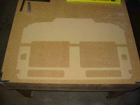 |
| This is the glassing of the 2nd side of the IP. The astute observer will notice that the image above doesn't have the heater holes in it, but this image does. I noticed right after I put the first ply of BID on the first side that I forgot these holds. I cut them out after the 1st side had dried. No problem. | 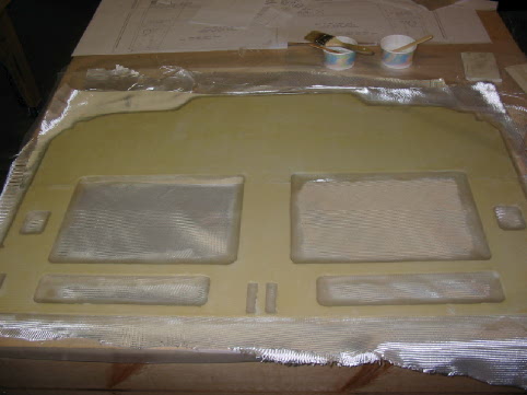 |
| Working on the IP stiffners. I had my first exotherm! (Note to self: when using dry micro, only mix very small amounts.) I was using dry micro to make a rounded edge for the BID. The lower stiffner came out fine. One minute I was working with fluffer nutter, the next it was like a hot brick. I managed to scrape the dry micro off the top stiffener, because it was very rough. | 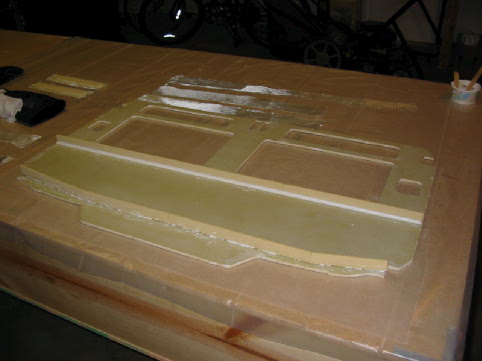 |
| Dry micro rounded edge. | 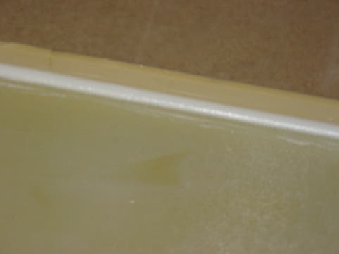 |
| View from the bottom. | 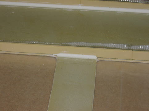 |
| I've read lots of different ideas about how to get the lip on the horizontal stiffeners. I took some long pieces of wood, around 1"x2" (scraps from cutting the chapter 5 jigs), rolled them in wax paper, and put them adjacent to the stiffeners. Here's a shot of what I'm talking about. | 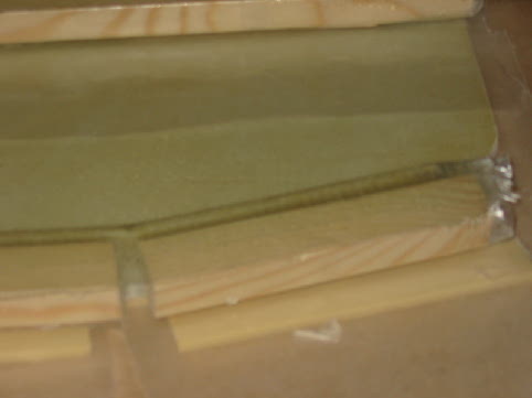 |
| Another image of the BID drying over the wax-covered wood. |  |
| After finishing the layup, I covered the stiffeners with more wax paper, and weighed it down with more wood scraps. | 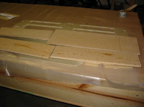 |
| This is how it turned out, after trimming the edge. | 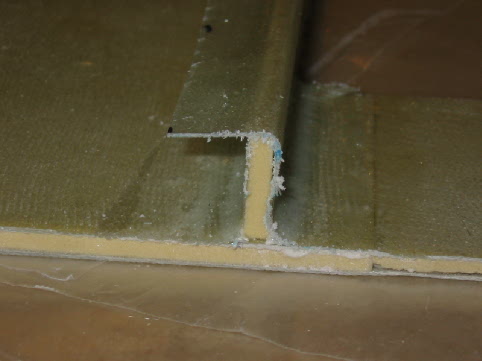 |
| Curing the vertical stiffeners. | 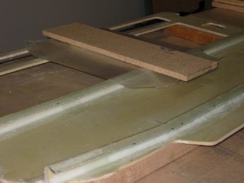 |
| Here's the completed IP, with stiffeners completed. I'm very pleased with how it turned out. | 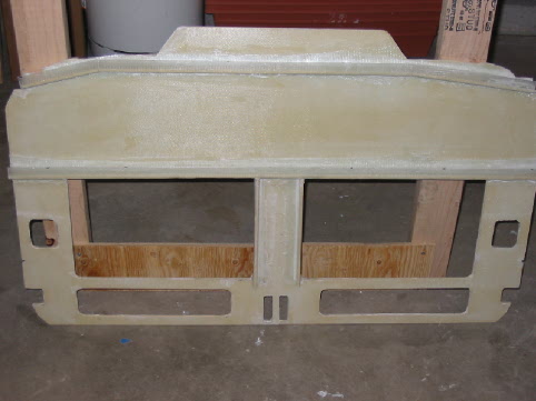 |
| Step 4. Landing Gear Bulkheads | |
| These are the landing gear bulkhead templates, cut out and placed over the .25" brown foam. Don't worry, I didn't cut up the original templates, these are copies. | 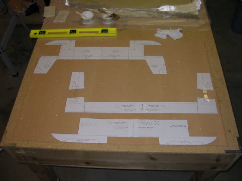 |
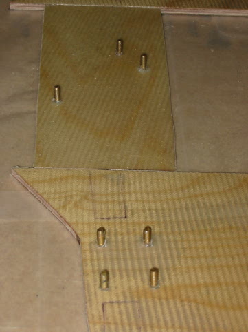
| The hardpoint templates over the 22-plies of BID. | 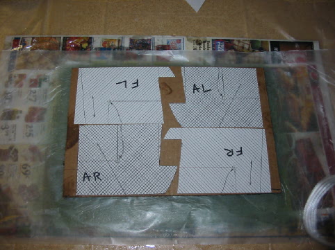 |
| The hardpoint block ready for cutting. | 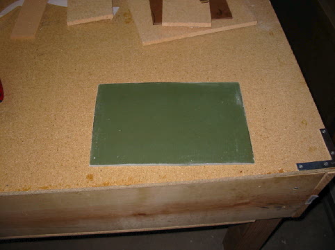 |
| Hardpoints are cut, and fitted into the landing gear bulkhead foam cutouts. Ready for glassing! Unfortunately, at this point I have to take a short break from working on the bulkheads; I'll be out of town for a business trip next week. | 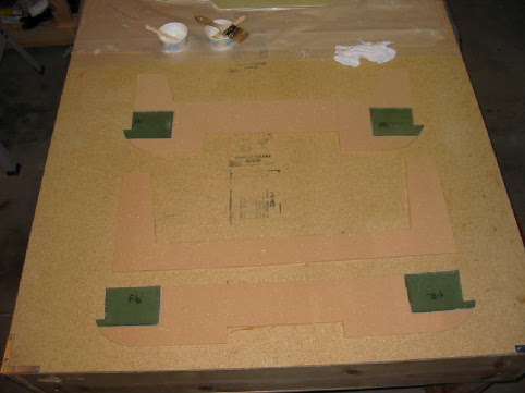 |
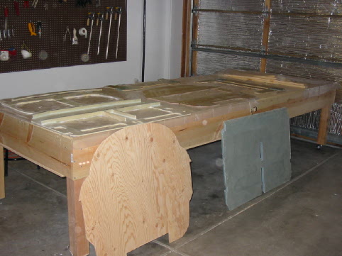
| I decided to split the jig tables up, so I'd have easier access to more working surfaces. On the far table you can see the front seatback on the left, and the landing gear bulkheads hardpoints on the right. On the near table you see the IP on the left, and the templates on the right. Lots of jobs in this chapter, and you can spend time working on lots of things while layups are curing. | 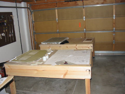 |
| Step 5. Firewall | |
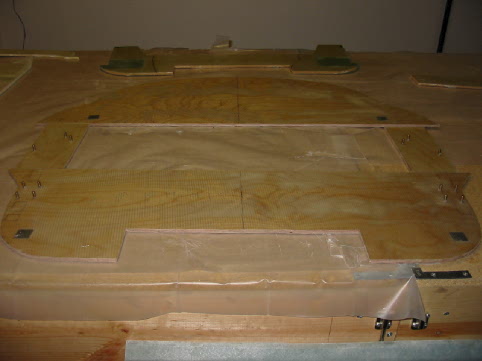
| Templates laid out for cutting the real firewall. For some reason this piece made me more nervous than any of the others. | 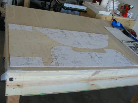 |
| Here's a shot of the aluminum engine mounts in place. I cut the aluminum with a jig saw, while the metal was held firmly in place with a vice grip. I also used the jig saw to cut out the 1" holes from the spruce, and then used a file to get the holes to exactly match the 1" blocks. A gentle tap from a hammer, and they went right in. | 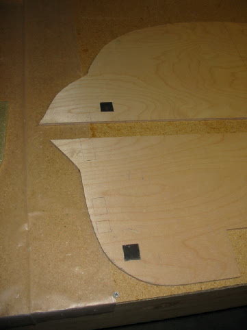 |
| 9/26/03 The firewall after installing the blind screws and glassing. |
 |
| 9/26/03 The completed firewall. |
 |
| 9/26/03 All the bulkheads. |
 |
<- Back to Chapter 3 | Home | To Chapter 5 ->
| Copyright (c) 2003, d'Armond Speers All Rights Reserved |
Last modified: Sunday, February 13, 2005 |