| d'Armond's Home | |
| Klingon | |
| Cozy Mark IV |
|
| Linguistics | |
| FTS |
Cozy Mark IV : Chapter 07
Fuselage Exterior
In this chapter you will finish the outside of the fuselage.
Pictures and commentary will go here as the work progresses. See also time and expenses related to this chapter.
- Step 1. Building the NACA Scoop
- Step 2. Contouring the Bottom
- Step 3. Glassing the Bottom
- Step 4. Contouring the Sides
- Step 5. Glassing the Sides
| Step 1. Building the NACA Scoop | |
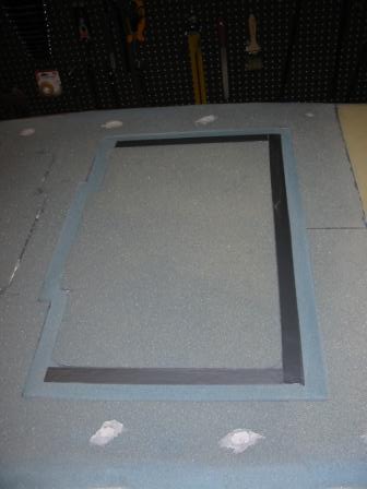
| 12/1/04 Masonite jig for the scoop. |
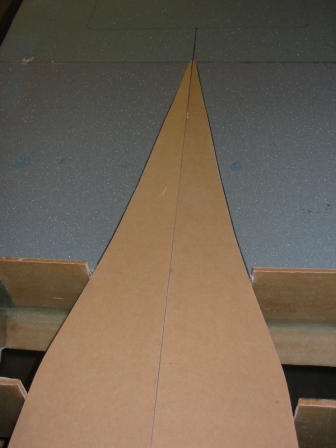 |
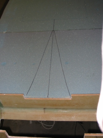
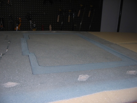
| Scoop drawn on the fuselage bottom. |
 |
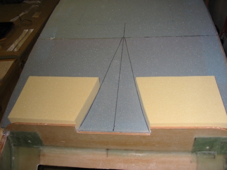
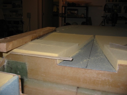
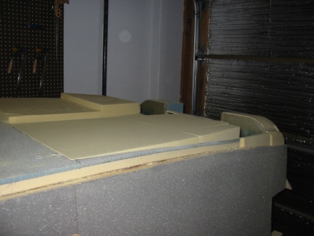
| Positioning the blocks of foam. |
 |
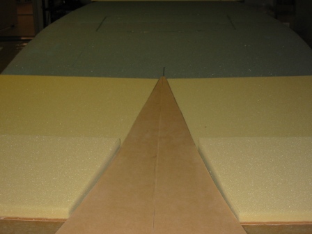
| Blocks in place, fitting with the template. |
 |
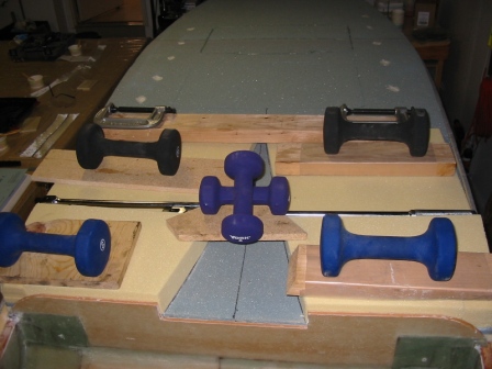
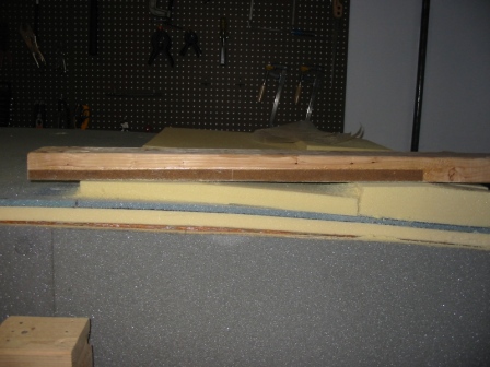
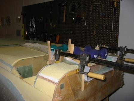
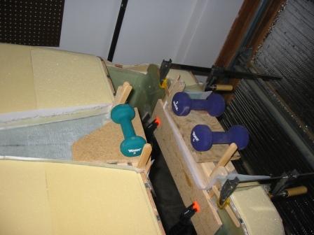
| Everything's weighted down while the micro cures. |
 |
| Sanding down the scoop with my 22" sanding block. |
 |
| A shot from the side... |
 |
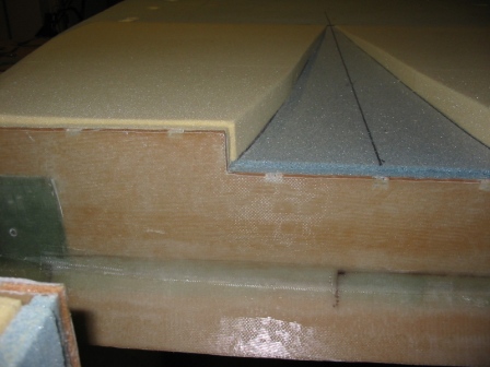
| One side of the scoop is sanded down, the other awaits. |
 |
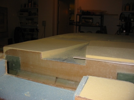
| Getting ready to sand the 2nd side of the scoop. One the left side you can see the 1/8" offset for the LG cover. On the right side you can see the 1/8" thick paint stirring stick I used to ensure the correct size offset. |
 |
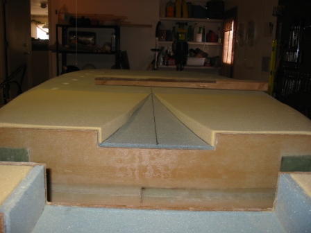
| And the scoop is finished. |
 |
| Cut the holes for the aluminum inserts. |
 |
| Aluminum inserts are cut and floxed in place. I got a band saw, based on builder advice, to cut the aluminum. |
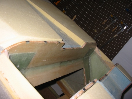 |
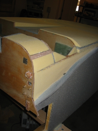
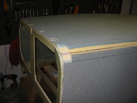
| Shaping the sides... |
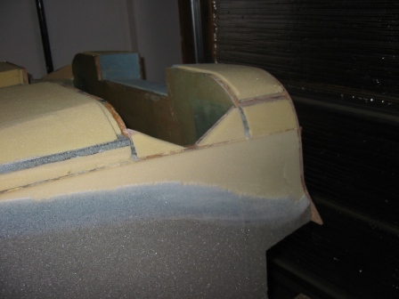 |
| The other side. From the FAQ I read that most builders tend to sand down to the electrical conduit, and you can see that I was no exception. |
 |
| Step 2. Contouring the Bottom | |
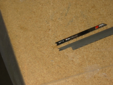
| Getting ready to trim the edges. I cut a band saw blade to fit into my jig saw. The dremel was great for making this blade. |
 |
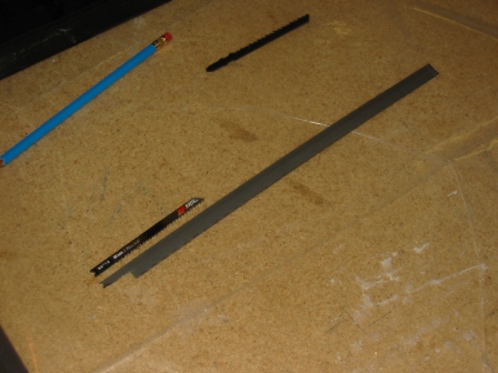
| The longest real jigsaw blade I could find was 6". This is my new blade next to a 4" blade for comparison. |
 |
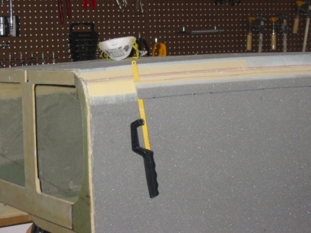
| I drew lines to help guide the cut at 45-deg. Here's about 2" of cut, which I wanted to check for the correct depth. |
 |
| Closeup... |
 |
| Following up with the 2nd cuts, with a hacksaw. Again I drew lines for guidance. |
 |
| Expert builder at work. |
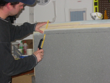 |
| 2nd cut along the top. If you look
below the lower cut, you can see a series of dings in the foam. As
I was making the lower cut with the hacksaw, a screw on the handle
impacted the foam. It took me a few inches of dings before I
noticed. So much for the expert builder. :/ |
 |
| Cuts are done, sanding it down to shape. |
 |
| View of the shaped side |
 |
| And on the other side as well. |
 |
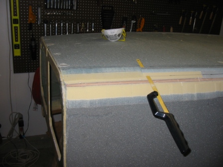
| 12/26/04 This is the 1/16" depression around the landing brake. It turns out that those little popsicle sticks we use for stirring epoxy are exactly 1/16" thick, so it was perfect for measuring progress. |
 |
| 12/26/04 Similar depression around F22. |
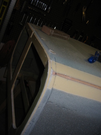 |
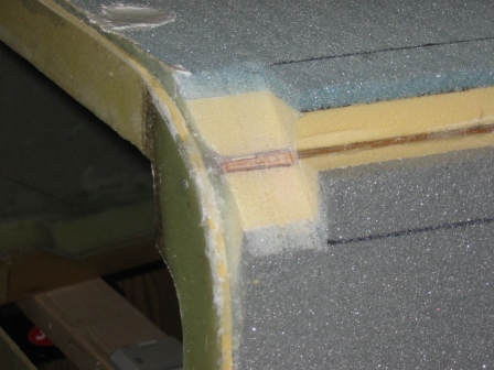
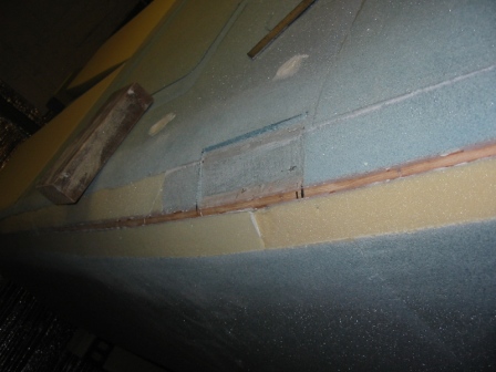
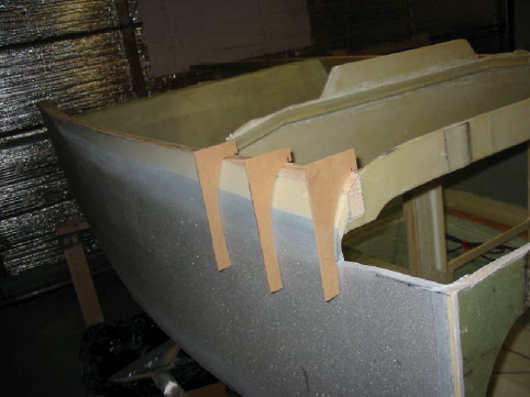
| 12/26/04 Marking the spot for the step reinforcement. |
 |
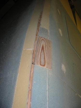
| 12/26/04 Removed the foam for the step reinforcement. This is going to be an awkward piece of wood to shape. |
 |
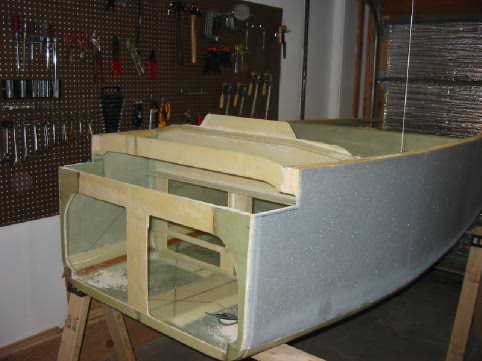
| 12/28/04 Yesterday I micro'd the step reinforcement into place, and today I sanded it down flush with the bottom. |
 |
| 12/28/04 Added the 1" duct tape around the landing brake. The divots filled with dry micro occurred when removing the frame from the bottom, after the inside of the bottom was glassed. |
 |
| 12/31/04 Glassed the scoop. It's incredible the contortions we go through to keep our glass laying down like we want it to. |
 |
| 12/31/04 Down glass, down! |
 |
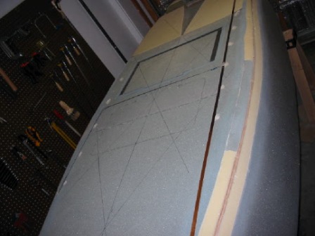
| 1/27/05 Close-up of the marker beacon antenna soldered to the RG-58/U coax, with toroids. |
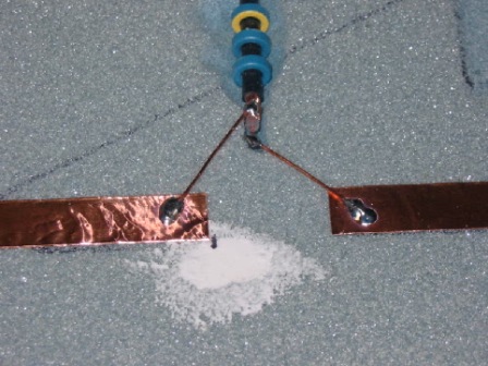 |
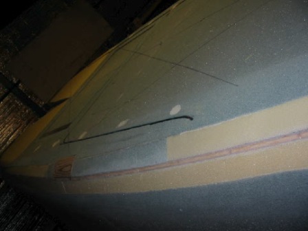
| 1/27/05 Marker beacon antenna runs fore-to-aft under the passenger side, and the coax runs at a 90-deg angle away from the antenna, just fore of the landing brake (and aft of the secondary landing brake). |
 |
| 1/27/05 The coax enters the cabin just fore of the IP. Don't expect the coax to bend sharply at 90-deg to enter the hole; the hole should be cut at an angle. |
 |
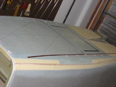
| 1/27/05 Ready for glassing! |
 |
| 1/27/05 A little closer... |
 |
| Step 3. Glassing the Bottom | |
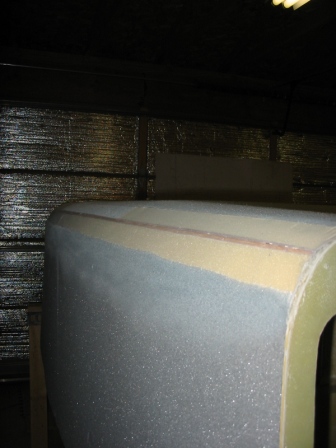
| 1/29/05 The bottom is now glassed and drying. |
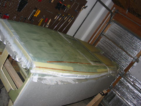 |
| 1/29/05 Back-side view of bottom glassed and drying. You can see the reinforcements in place here too. |
 |
| Step 4. Contouring the Sides | |
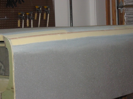
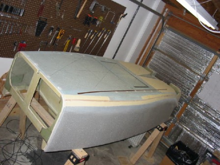
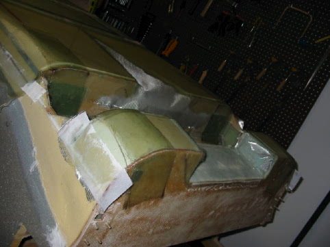
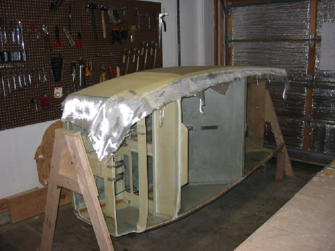
| 2/2/05 Good view of the contour, conforming to the templates. This is the passenger side. |
 |
| 2/2/05 The canard cutout. |
 |
| Step 5. Glassing the Sides | |
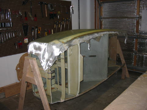
| 2/2/2005 Getting ready... |
 |
| 2/12/05 The 2nd ply is down... |
 |
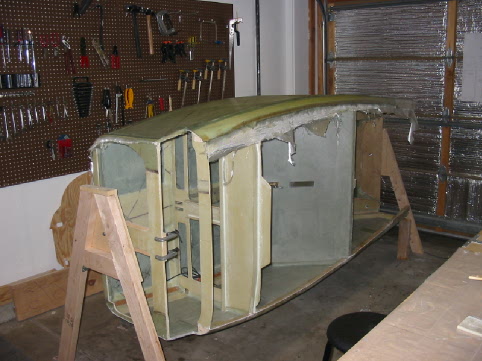
| 2/12/05 The 3rd ply is down... |
 |
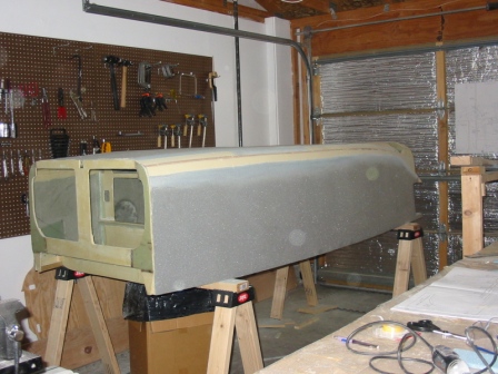
| 2/12/05 All done, just letting everything dry! |
 |
| 2/13/05 Alec and I take the bird for a spin. |
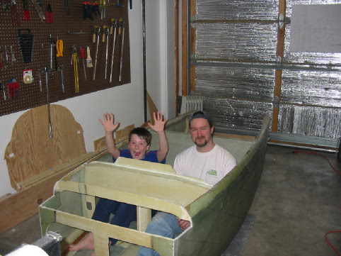 |
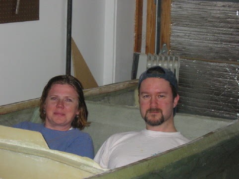
| 2/13/05 Amy and I check out how Cozy it is in there. |
 |