| d'Armond's Home | |
| Klingon | |
| Cozy Mark IV |
|
| Linguistics | |
| FTS |
Cozy Mark IV : Chapter 9
Main Landing Gear and Landing Brake
In this chapter you will install the main landing gear and landing brake.
Pictures and commentary will go here as the work progresses. See also time and expenses related to this chapter.
- Step 1. Landing Gear Bulkhead Reinforcements
- Step 2: Preparing the Strut for Installation
- Step 3: Attach Tabs & Installation
- Step 4: Landing Gear Cover
- Step 5: Installing Axles, Brakes and Brakelines
- Step 6: Constructing the Landing Brake
| Step 1. Landing Gear Bulkhead Reinforcements | |
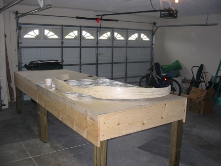
| 7/3/05 New shop Set up the new workshop in our new house in Florida. Went from a 2-car to a 3-car (1-plane) garage. Much nicer! |
 |
| 7/3/05 Reinforcing layups Here are the reinforcing layups on the front LG bulkhead. |
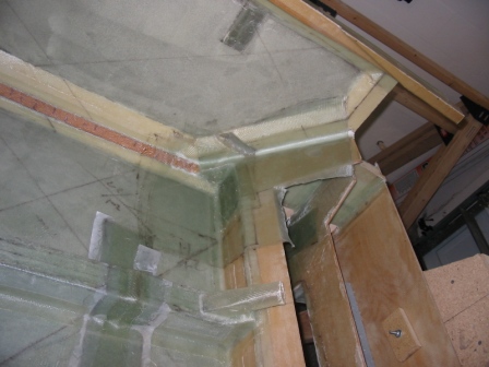 |
| 7/6/06 Reinforcing layups ...and on the rear LG bulkhead. The reinforcements for the middle are done also, just not shown here. |
 |
| Step 2: Preparing the Strut for Installation | |
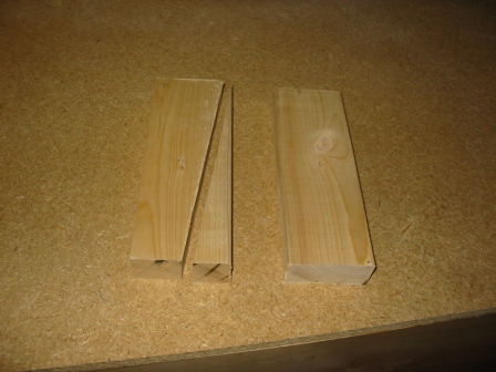
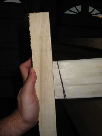
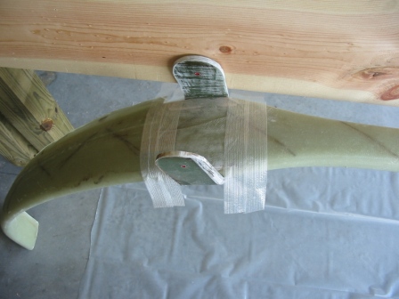
| 7/9/05 LG Strut To get the 8-degree incline, I cut a board at 8-degrees for reference. |
 |
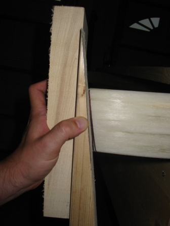
| 7/9/05 LG Strut I put a mark on the top of the strut at where it measured 95", lined up the 8-deg board to that mark, and drew a line. |
 |
| 7/9/05 LG Strut The resulting 8-degree line drawn on the strut. |
 |
| 7/9/05 LG Strut I secured the strut to the work bench with a long 2x4, to keep it steady while I cut it. |
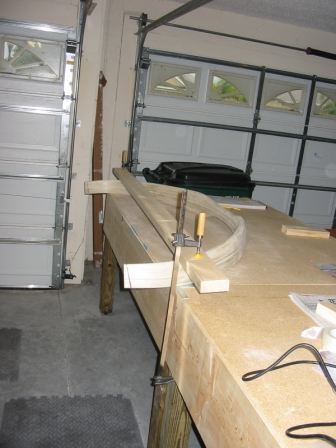 |
| 7/9/05 LG Strut At first I tried to use the jig saw, but it got so hot that I couldn't use it for more than a few seconds. Once I had the cut deep enough I switched to using the hacksaw. The cut was much faster an easier with the hacksaw, but I was worried because the blades are so flimsy, that they wouldn't keep a straight cut. |
 |
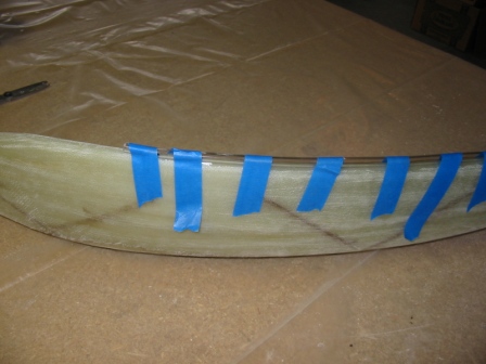
| 7/9/05 LG Strut But as you can see, the cut came out nice and straight. |
 |
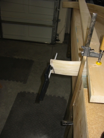
| 7/9/05 LG strut layups The strut raised on nails on the workbench, ready for glassing. |
 |
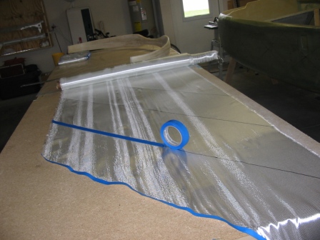
| 7/9/05 LG strut layups I measured out the UND at the correct angle, drew cut lines, and taped it off with painter's tape. This ensured that the UND fibers kept straight while waiting for their turn. |
 |
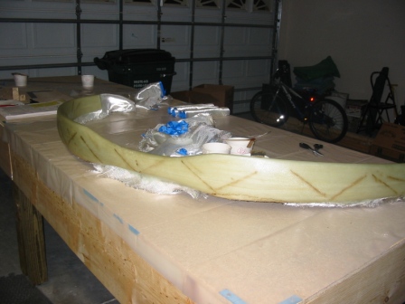
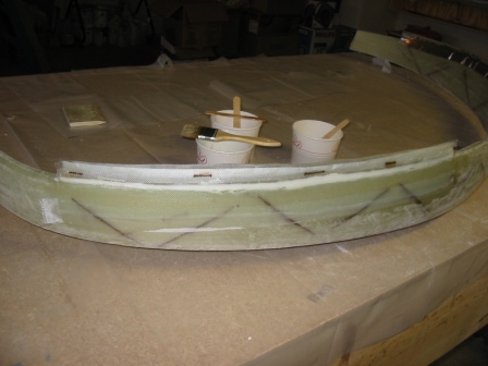
| 7/9/05 LG strut layups The first 4 plies of UND are drying. It's the end of a long day. |
 |
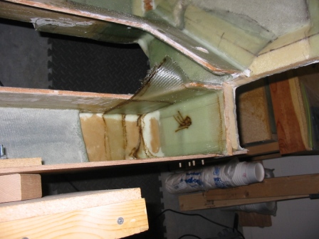
| 7/10/05 LG brake line This is 3/8" OD vinyl tubing. The painter's tape is keeping it straight and in position while the 5ME dries. |
 |
| 7/10/05 LG brake line The 2-ply BID tape is in place over the brake line, against the aluminum tape. Many builders reported using something different from the alum tape, but I found it easy to work with and strong enough for this purpose. To each his own I guess. |
 |
| Step 3: Attach Tabs & Installation | |
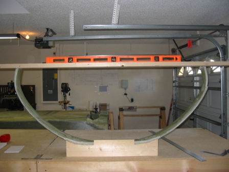
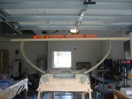
| 7/14/05 Attach tabs Leaned the strut up against the table, made the appropriate marks on the plywood board and floor, and shimmed the strut level. The 2x4 on the floor in front of the strut ensures the LE is the correct distance in front of the board. |
 |
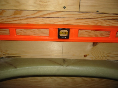
| 7/14/05 Attach tabs Ensuring A is level. |
 |
| 7/16/05 Attach tabs The jig box fit in place and level. |
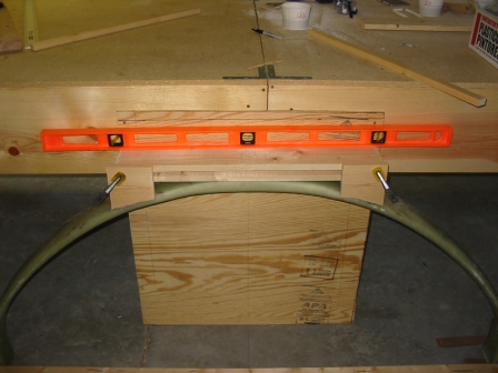 |
| 7/16/05 Attach tabs The box is done, and the strut is on the table (with appropriate lines drawn for the FSs on the table). Perfectly level with no adjustment! Though I did have to shim the back of the box a bit, to get the LE lined up with FS 108.25. |
 |
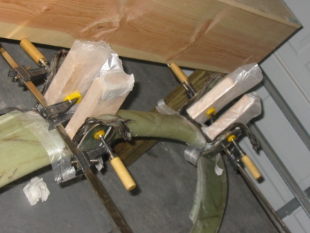
| 7/16/05 Attach tabs 25 plies of UNI and 20 plies of BID, drying. I had no trouble with the clamps causing the plies to slide around, as described in the FAQ. |
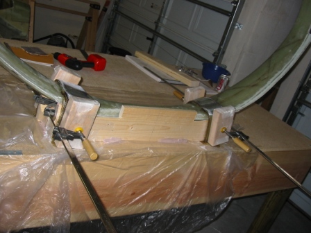 |
| 7/17/05 Attach tabs I made a small round jig to help ensure a good, round tab. |
 |
| 7/17/05 Attach tabs The outside tabs have been finished. |
 |
| 7/17/05 Attach tabs In preparation for doing the insides of the tabs, I put down some packing tape. This will make it easier to cut the glass away from the strut, trim with the tab. (Lesson learned from the outside tabs.) |
 |
| 7/17/05 Attach tabs Inside tab layups are done, clamped, and drying. |
 |
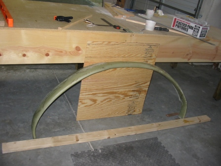
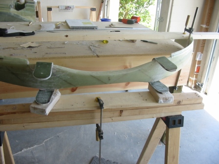
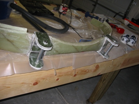
| 7/26/05 strut install This is the trial fit of the strut. I still don't have the 1/4" aluminum for MG-1, so the full install won't be for a little while. I drew the FS lines on the floor to check the position of the LE, and found that it was just a bit forward. Will adjust some more later, before installing for real. |
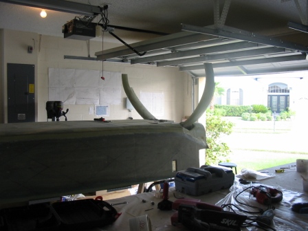 |
| 7/26/05 strut install It is, however, perfectly level, which is very cool. |
 |
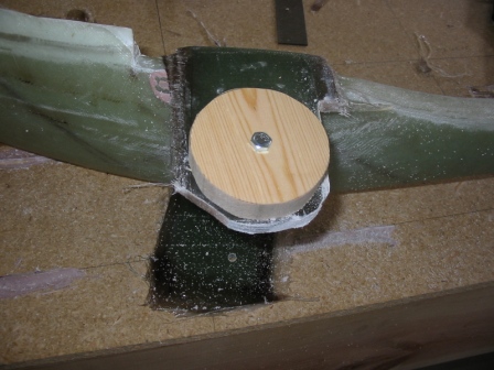
| 8/09/05 attach tabs Cut holes in tabs with the 3/4" counterbore. Had to sand the holes a bit with a file to get the rods to fit. |
 |
| Step 4: Landing Gear Cover | |
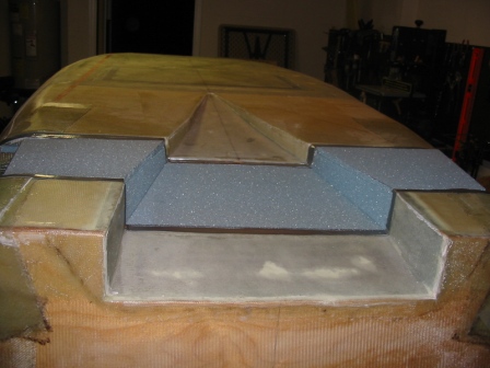
| 7/27/05 LG cover Here you can see the duct tape and shelf made for the LG cover. |
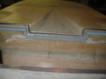 |
| 7/27/05 LG cover The 3/8" PVC foam cut and in place for the cover. This part was fun! |
 |
| Step 5: Installing Axles, Brakes and Brakelines | |
| Step 6: Constructing the Landing Brake | |
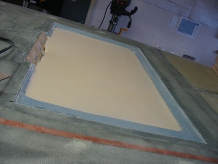
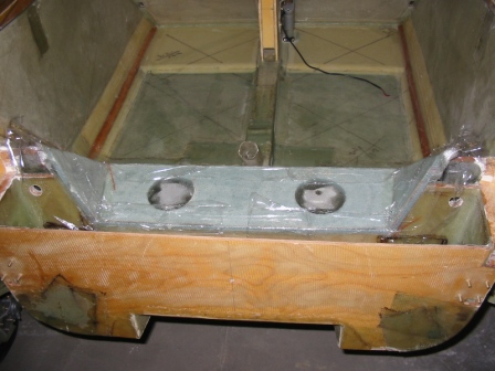
| 7/31/05 Cut LB loose Not the cleanest cut. You can see some places where the 5ME just didn't want to let go. |
 |
| 8/12/05 Sanding LB LB-23 is installed. This shot is after sanding 1/8" deep into the foam and radiusing the corners. |
 |
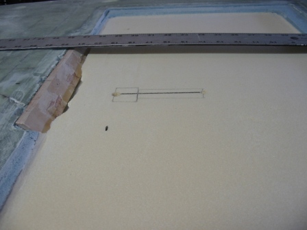
| 8/12/05 LB I started to cut out the hole for the LB, but decided to wait until I've received the LB actuator from Wayne Lanza. So this part is on hold. |
 |
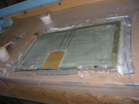
| 9/11/05 Landing brake Glassing the inside of the LB. |
 |
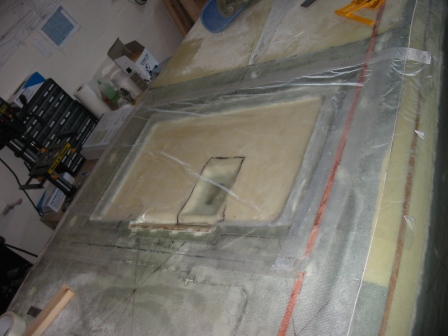
| 9/11/05 Landing Brake Plastic covering the LB hole, so that when the LB is put back in place it doesn't cure to the fuselage bottom. |
 |
| 9/11/05 Landing Brake Floxed the hinge in place (which would detach later), and weighted down the partially-cured LB. |
 |
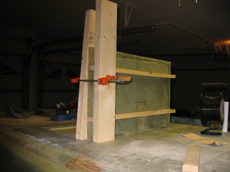
| 9/13/05 Landing Brake Some boards are called to service to hold the LB in place while I drill and tap holes through the hinges to bolt it in place. |
 |
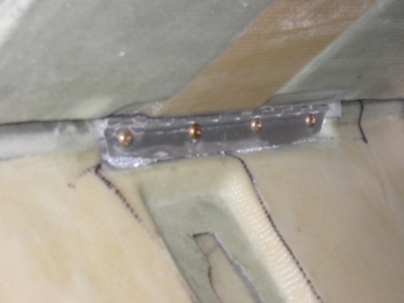
| 9/13/05 Landing Brake Hinge bolted in place. |
 |
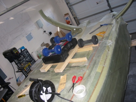
| 9/4/05 LB-18 brackets These turned out nice. |
 |
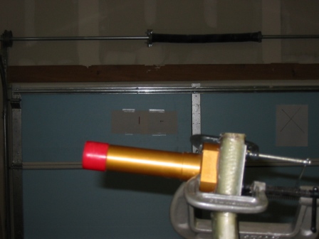
| 5-16 Axle attach At this point the strut has been trimmed to make room for the caliper, and the 2-plies BID have been attached. I used a laser level to the mark on the wall (visible in the background), rather than the tube sighting method described in the plans. |
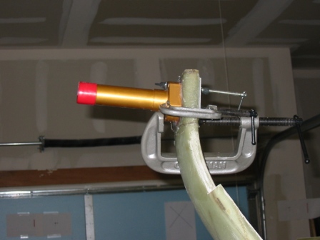 |
| 5-16 Axle attach Another view of the axle drying in place with the marks on the wall. |
 |
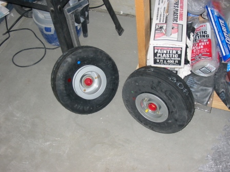
| 5-17 The tires have been installed on the wheels, and are waiting for the axles to be ready. |
 |
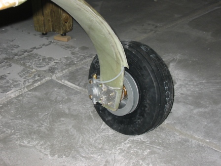
| 5-17 Wheel attach The plane is on its wheels! The brake line has been run on the inboard side up to the conduit... |
 |
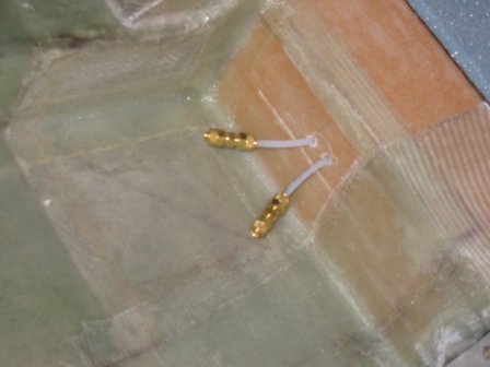
| 5-17 Brake lines ...and inside through the fore LG bulkhead.
|
 |
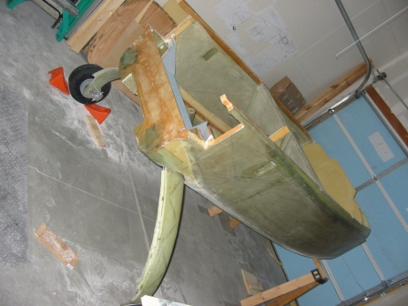
| 5-17-07 Wheel install A farther view of the plane on its wheels.
|
 |
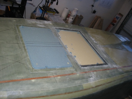
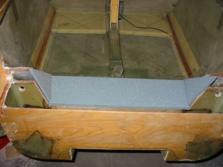
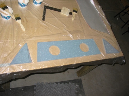
| 5-17 Gear box closure Trial fitting the foam for the top of the gear box. |
 |
| 5-17-07 LG box cover Getting ready to glass... |
 |
| 5-18-07 LG box Drying in place. |
 |