|
|
|
|
|
|
| Cozy Mark IV |
|
|
|
|
|
|
Cozy Mark IV : Chapter 13
Nose and Nose Gear
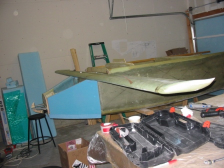
In this chapter you will build a nose gear box which contains the nose gear strut and worm gear retraction assembly. The box consists mainly of two glass/foam/glass side panels with built-in hardpoints for mounting the nose gear hardware.
Pictures and commentary will go here as the work progresses. See also time and expenses related to this chapter.
|
||||||||||||||||||||||||||||||||||
Some thoughts on 10/28/07 This is the longest and most expensive chapter yet! Lots of modifications to the plans (electric nose lift, lights in the nose, gear doors, different rudder pedals, master cylinders and reservoirs). Everything that differs from the plans adds time, expense, and uncertainty. If these mods weren't so well proven by previous builders I would be much more hesitant to put them on my plane.
|
||||||||||||||||||||||||||||||||||
|
(nothing to see here, move along) |
|
|
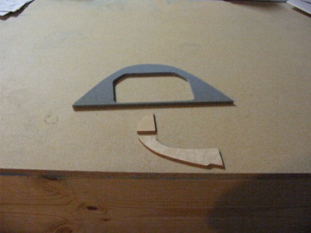
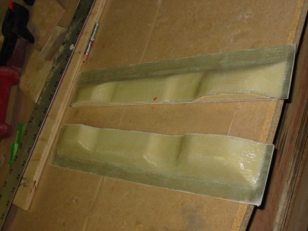
5/5/2007 Cutting out NG-30's from 1/4" foam. |
|
|
5/6/2007 Made the 1/4" birch doublers with aluminum inserts and the 1/8" aluminum doublers. |
|
|
5/6/2007 The inside surfaces of NG-30 are dry and carefully matched, ready for the next step. |
|
|
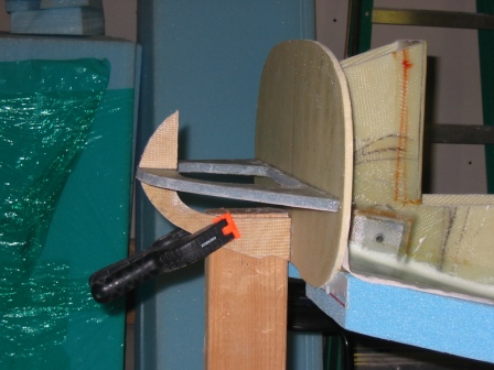
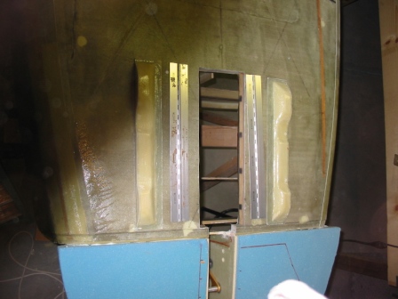
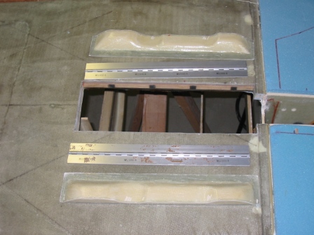
5/6/2007 Cutting the depressions for the hardpoints for the nosegear mounting brackets. The bottom hole is not getting a hardpoint because I'm not using the worm drive. |
|
|
5/6/2007 The outside surfaces of NG-30 are completed and drying. |
|
|
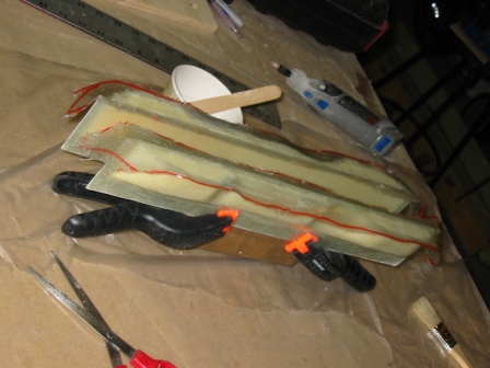
5/7/2007 Drilling the holes through NG-30s with the drill press. |
|
|
5/8/07 Floxed NG1-L to MKNG6 |
|
|
5/11/07 Floxed NG3 & NG4 to NG-1L at 6.79". |
|
|
(not using the worm drive assembly, so no pics here) |
|
|
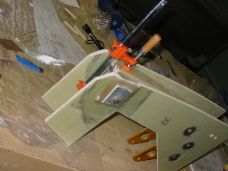
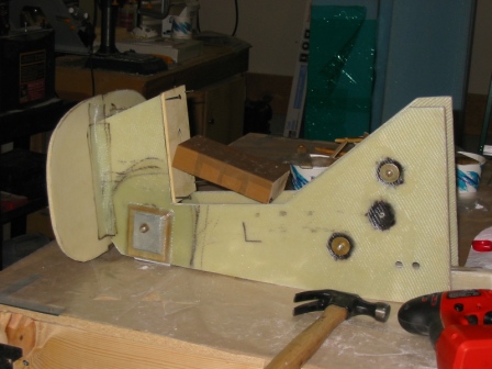
5/11/07 Installed F-0 and F-5 to NG-30 assembly. |
|
|
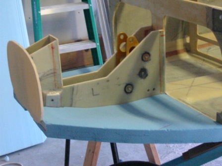
5/19/07 Floxed NG-30 assembly to F-22. |
|
|
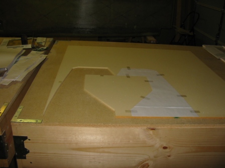
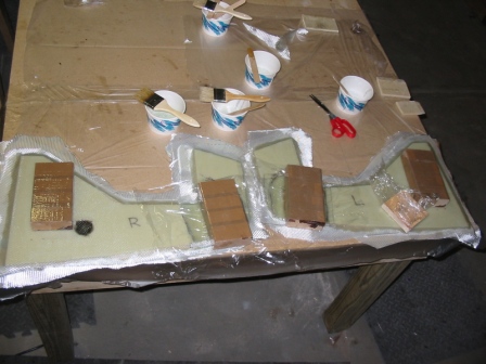
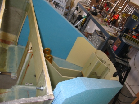
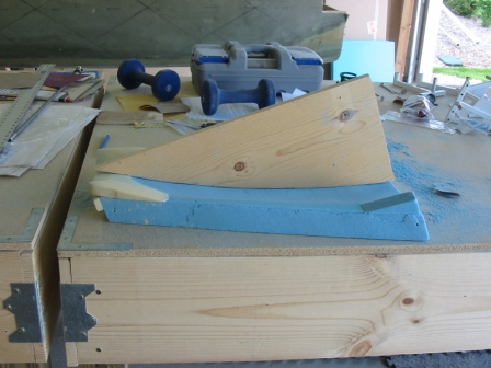
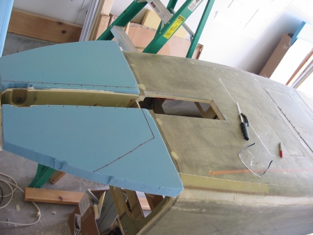
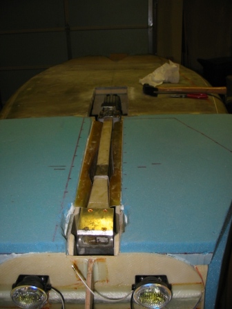
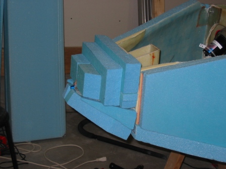
5/19/07 Nose floor Cut out and contoured nose floor pieces. I'm very happy with how this turned out. I drew lines on the pieces to mark the location of the transitions, and then used my dremel with the depth control attachment (whatever it's called) to make each step the correct depth. I moved a long ruler along each piece with the dremel over it. Once it was done it looked like a bunch of steps down to the center. I then used sandpaper to even it out, to get the shape you see here. |
|
|
5/19/2007 nose floor Micro'd in place |
|
|
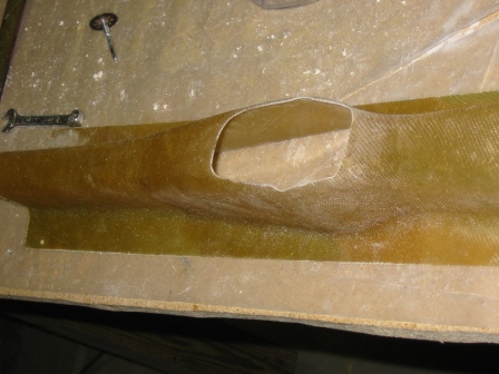
5/19/2007 nose Cut out NG-31 & NG-32. Okay, I must admit, I spent about 45 minutes just staring at the plans and M-19 trying to figure out what these pieces were. In the plans there's only a side view, and I was just so confused. I finally went and looked at Rick Maddy's site to see what he did. The cutout for NG-31 wasn't labeled, so I suppose you're just supposed to know what it is. |
|
|
5/20/07 Nose floor Foam inserts to make a smooth transition to the floor aft of F22. I shaped these by hand to make a close fit, attached them with 5ME, and then sanded them some more to get a really nice transition. Later when the floor is glassed, I added some dry micro to make it perfect. |
|
|
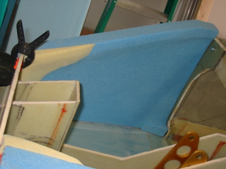
5/20/07 nose floor Glassed the top of the nose floor. You can see I used dry micro for smooth transitions, though it wasn't explicitly called out in the plans. By this time I guess you're just supposed to know what you're doing. |
|
|
5/20/07 Checking position for the install of NG-31 and NG-32. |
|
|
5/20/07 NG-31 & NG-32 in place with flox to cure. |
|
|
6/2/07 I have the sides cut, trial-fitting the B pieces. These (B) are held in place with small dabs of 5ME, to minimize the micro line between A and B when I sand. |
|
|
6/2/07 5ME C in place back against F22. |
|
|
6/2/07 Now that's a pretty sight! |
|
|
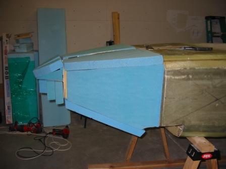
6/2/07 Cut a template to match the outside shape of the nose floor, and sanded the sides to match. Lots of foam dust! Wear a mask! |
|
|
6/2/07 Nice shape, good fit. |
|
|
6/2/07 Another view of the left nose side. The 5ME got in the way a little, but not bad. |
|
|
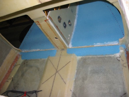
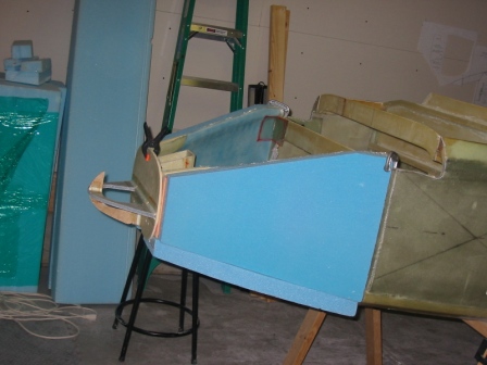
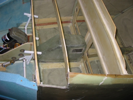
6/2/07 Insides have been glassed and are now installed. |
|
|
6/3/07 Finishing the canard install bit. Had to cut away the top of the nose sides to accommodate the canard, but of course there were no dimensions in the plans for this. It's not like we didn't know until now what shape to make it! Of course I cut away too much and had to add some foam back. Not ruined, just a little annoying. CNL bushings are floxed in place. |
|
|
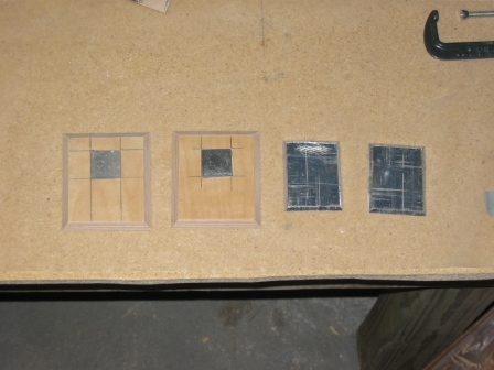
6/3/07 This is the .2" high density foam for the rudder pedal pivots. |
|
|
6/3/07 Floxed in place with a block to hold it parallel and vertical. |
|
|
6/3/07 The nutplate flush with the pivot block. |
|
|
6/3/07 4 plies BID, and that's the end for today! |
|
|
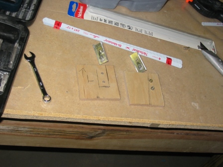
10/13/07 Cut brackets for the attach of the 10-54 cylinders. The brackets are cut from a 3/4" square aluminum tube, about 2" long. |
|
|
10/13/07 Birch plywood inserts that the brackets will attach to, for added strength. The nuts are embedded in the underside, so that when the inserts are floxed in place the nuts will be there already. |
|
|
10/13/07 The cut-out for the birch inserts. |
|
|
10/13/07 Birch inserts floxed in place and covered with 2-ply BID. |
|
|
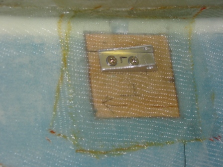
10/13/07 Brackets bolted to the inserts. |
|
|
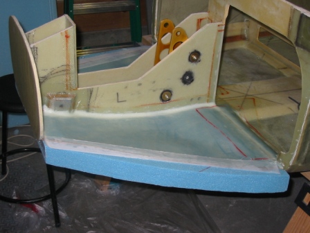
10/13/07 The completed assembly. |
|
|
10/13/07 And from the other side. |
|
|
5/26/07 Jumping around a bit here. Before I put the sides of the nose on I want to finishing positioning the mounting brackets for the nose retract motor. To do this I need to check the position of the motor with the nose gear extended and retracted, and to check it retracted, I need to cut the hole in the fuselage bottom to retract it. Also cut a bit from the bottom of F22 to allow the gear to retract further inside, to make room for nose gear doors. |
|
|
5/26/07 Sanding and checking the doors to allow sufficient clearance for the nose wheel. |
|
|
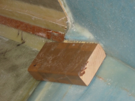
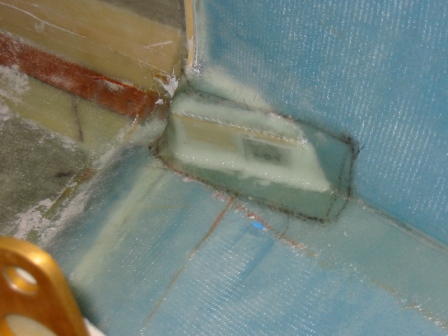
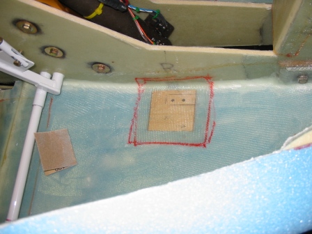
5/27/07 Hard to see, but I sanded away the foam between the outside and inside fiberglass, where I will install the birch inserts. |
|
|
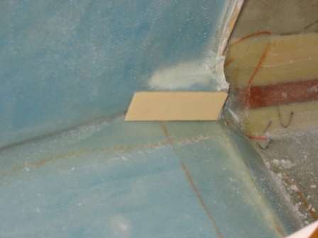
5/29/07 I cut a 45-deg bevel on the top and bottom sides of the birch inserts, for flox corners. Floxed these in place. |
|
|
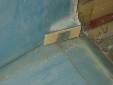
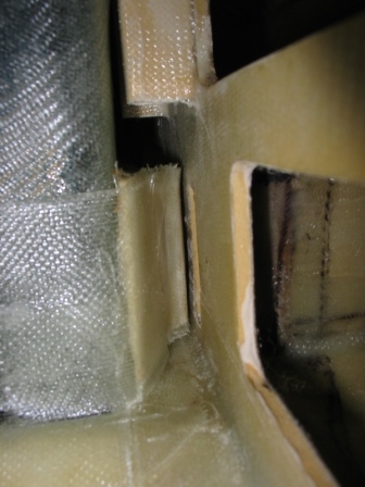
5/29/07 1 ply BID to flox corners. |
|
|
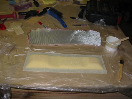
5/30/07 2 plies BID on the inside surface of the gear doors. |
|
|
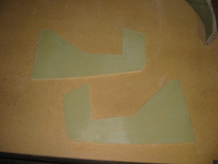
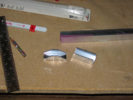
5/31/07 Cut the doors in half |
|
|
5/31/07 Cut a channel for flox corners of the inside of the doors |
|
|
5/31/07 Another view of the doors |
|
|
5/31/07 1 ply BID inside the doors with flox corners. |
|
|
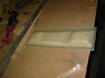
6/1/07 What the doors will (hopefully) look like |
|
|
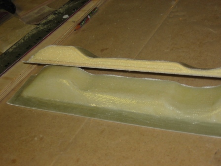
6/1/07 Another view. Can't do anything further on this for now, until the hardware arrives. |
|
|
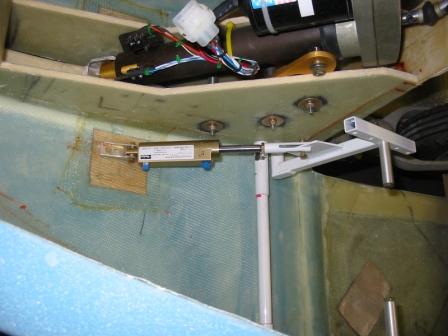
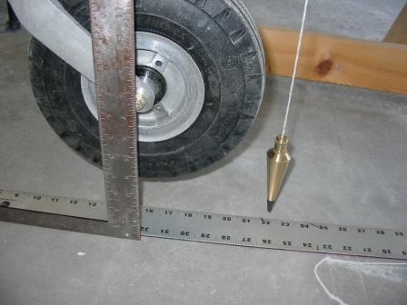
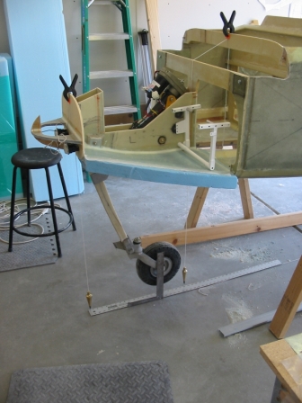
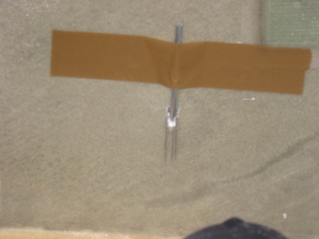
6/2/07 Turned the fuselage back over, installed the nose gear and the retract motor, and carefully (manually) extended the nose gear until it was at F16. You can see the plumb bob hanging down from F22, right at the 22" mark, and the square lining up with the bolt on the wheel at F16. |
|
|
6/2/07 Another view |
|
|
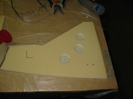
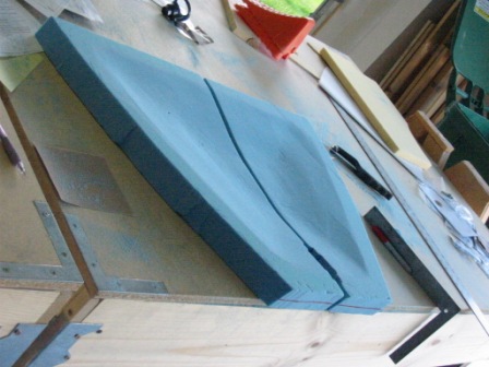
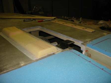
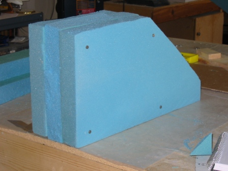
9/21/07 Foam blocks preparing to become a mold for the nose wheel well. |
|
|
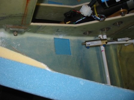
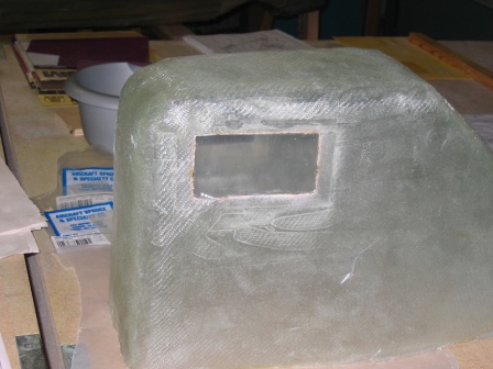
10/13/07 The Plexiglas window in the wheel well, so we can see if the nosewheel is retracted or not. |
|
|
10/14/07 The hole I had to cut in the strut cover to make room for clearance for the nose retract piston. |
|
|
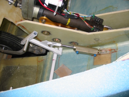
10/14/07 The nose gear retracted into the strut cover. |
|
|
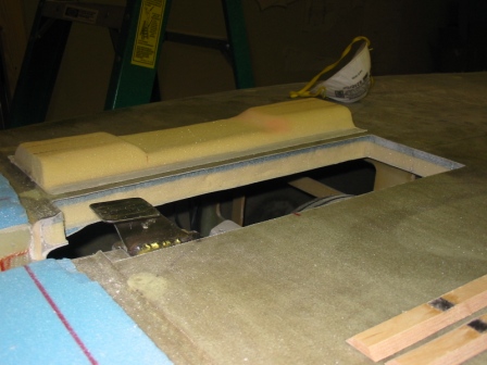
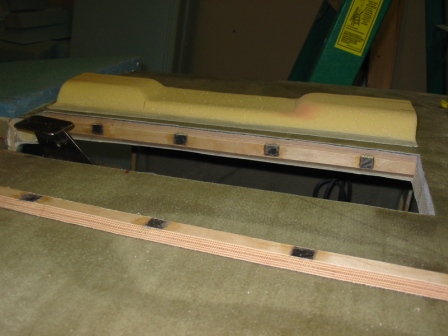
10/14/07 The nose wheel well in place. I was surprised how close to the fore side of the IP it turned out to be. It's farther forward in the plans, though Nat did indicate that it could possibly be farther back. Time will tell if this will cause me problems. |
|
|
10/14/07 A shot of the wedge that redirects heat from the duct to the sides. You can see here how close the wheel well is to the IP. |
|
|
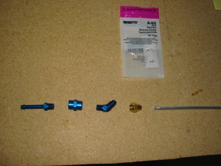
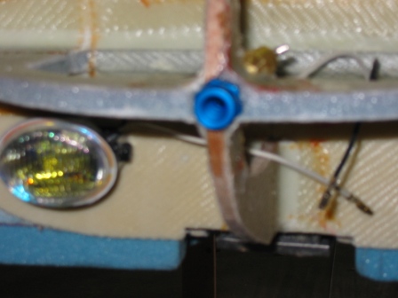
10/20/07 The parts for the removable pitot tube and line. I got the nipple, adapter and 45-deg angle as called out in the plans, but I had to buy the brass adapter separately to complete the linkage to the aluminum tube. |
|
|
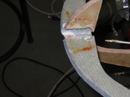
10/20/07 Drilled a hole directly in the center of NG-31 and enlarged it so the assembly will fit. |
|
|
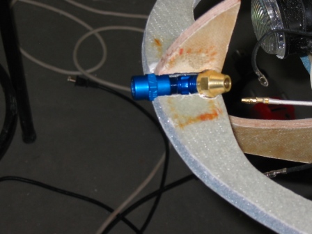
10/20/07 This is how the whole thing fits. |
|
|
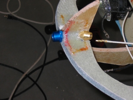
10/20/07 Floxed in place, and added back the 2-ply BID to give it the same strength it had before. |
|
|
10/20/07 A (fuzzy) view from the front. |
|
|
10/20/07 The aluminum tube routed into place. |
|
|
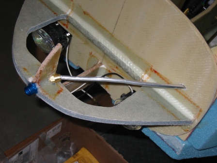
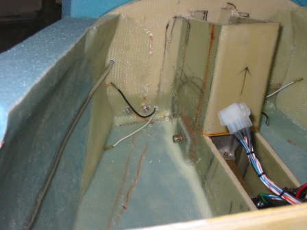
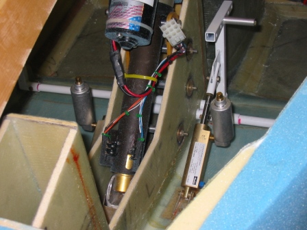
10/20/07 An interesting problem. Since I'm (a) putting taxi & landing lights in the nose and (b) not using a pre-fab nose, how to get the foam in place for shaping the nose? I cut small foam pieces similarly to how the nose floor pieces were cut and 5ME'd them in place, so that the bottom compartment is hollow. I'm basically winging it here, we'll see how well it works. Later I'll shape the Plexiglas, cut out holes in the bottom of the nose, and figure out how to glass the inside to protect the foam from the heat. Instead of a ballast compartment, the access door here will allow access to the lights. I'll need to remember to watch out for the pitot tube when I'm digging this foam out! |
|
|
10/20/07 My best guess as to the foam blocks around the lights. |
|
|
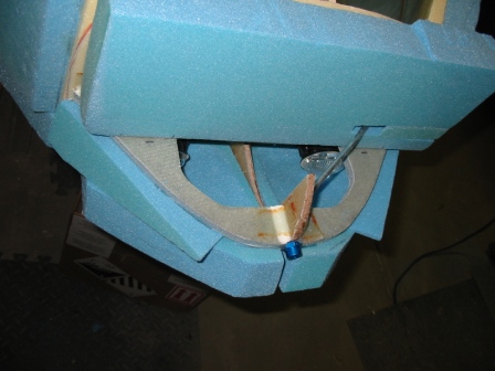
10/20/07 Everything's in place. |
|
|
10/20/07 I drilled holes and brought the wires to the lights aft of F0. You can also see here the aluminum tube for the pitot line. |
|
|
10/20/07 The static line as per plans. |
|
|
10/21/07 Before... |
|
|
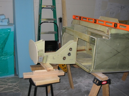
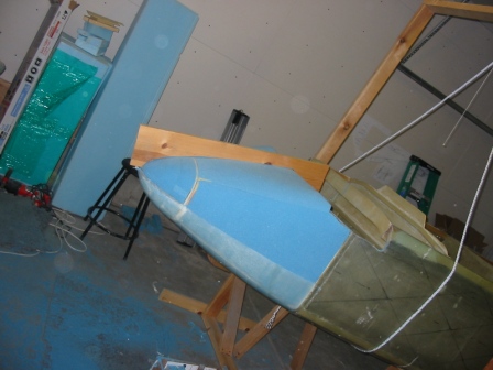
10/21/07 After! (The top, which is on the bottom in this shot as the plane is upside down, has not finished being shaped yet, which is why it looks a little bulgy there in the front.) You can also see here the birch support block for the nose puck. The gear is extended to ensure no conflict. |
|
|
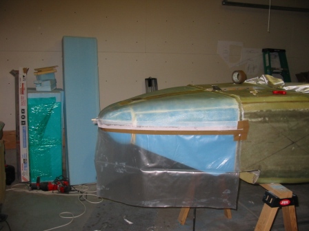
10/27/07 Glassed the bottom side of the nose. |
|
|
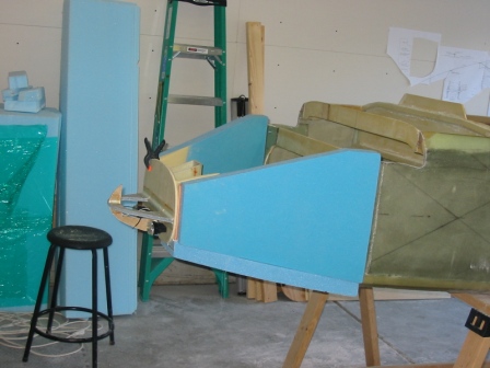
10/28/07 Rolled the plane over to shape the top of the nose. This is the template I made for getting the shape right. Testing here with the top piece of the nose off. |
|
|
10/28/07 While the top is off, I installed the master cylinder reservoirs, which had been on back-order. |
|
|
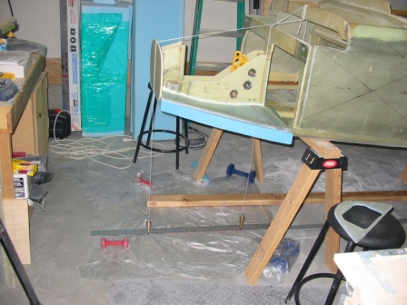
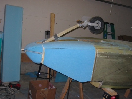
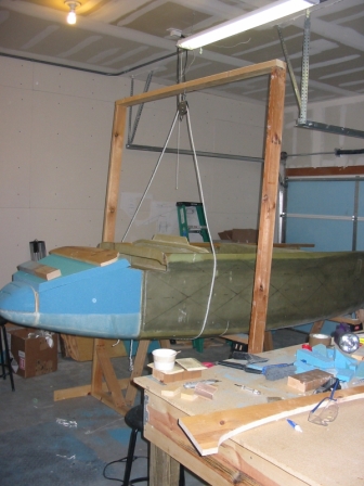
10/28/07 This plane is getting too heavy to roll over by hand! Long ago we made A-frame rotisserie stands for turning the fuselage, but I can't use the front one anymore because of the nose. The A-frame is still attached to the back, but for supporting and turning the front I made this large frame, with a pulley and rope, to turn the plane. Usually the plane is on saw horses, but to turn it I lift it up while someone removes the saw horses, and the plane rolls easily over. Replace the saw horses, and voila! The first time we did this, I said to my son that this is either really clever or really stupid, but I wouldn't know which until we tried it! I can almost do this myself, except for moving the saw horses. |
|
|
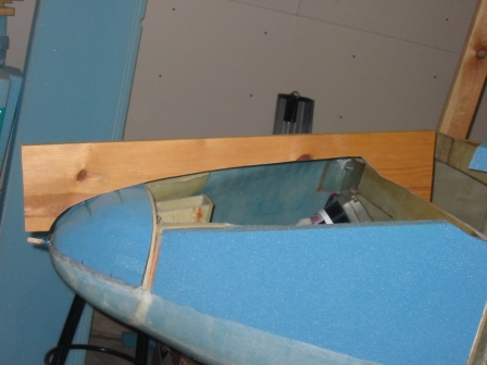
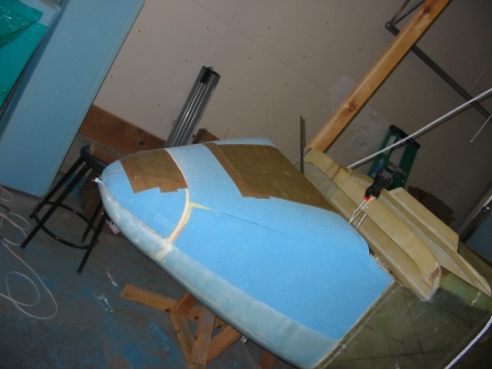
10/28/07 Nose top back on, and sanded to conform to the template. Look at that, it looks like the nose of an airplane! |
|
|
10/28/07 One inch depression over F-0 for taping. |
|
|
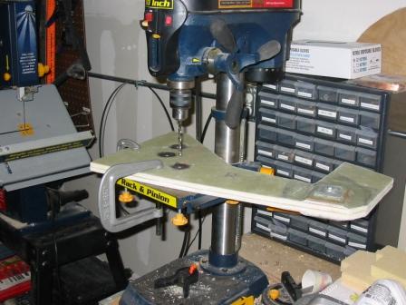
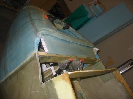
10/28/07 I cut the nose strut from the bottom, removed it from the plane and drilled the 3/16" hole through NG-3 for the machine head screw that gets installed here. Yup, lifted the whole thing right up onto the drill press. |
|
|
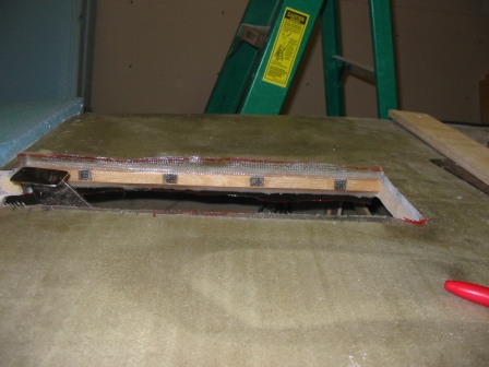
10/28/07 Three plies BID over box-sealing tape on the nose, curing. These pieces will become the doors. My front nose door is not a ballast compartment, but an access door for the taxi and landing lights. I'll be adding the Plexiglas windows later. |
|
|
11/21/2007 Working on nutplates to secure nose door and the torsional support from the fore of F-22 to the top. |
 |