| d'Armond's Home | |
| Klingon | |
| Cozy Mark IV |
|
| Linguistics | |
| FTS |
Cozy Mark IV : Chapter 19
Wings and Ailerons
In this chapter you will build jig templates, cut foam cores, lay up shear webs, spar caps and skins, install attachment reinforcements, build and rig ailerons and install wing-mounted aileron controls.
Pictures and commentary will go here as the work progresses. See also time and expenses related to this chapter.
Step 1: Building the Wing Jigs Completed Step 2: Setting up the jigs Completed Step 3: Cutting foam cores Completed (left wing, right wing) Step 4: Assembly of foam cores and lay up of shear web Completed (left wing, right wing) Step 5: Bottom spar cap Completed (left wing, right wing) Step 6: Bottom skin Completed (left wing, right wing) Step 7: Top spar cap Completed (left wing, right wing) Step 8: Top skin Completed (left wing, right wing) Step 9: Wing ribs in process (left wing & right wing) Step 10: Ailerons Step 11: Controls Step 12: Attachment, wing to center spar
| Step 1: Building the wing jigs | |
| Step 2: Setting up the jigs | |
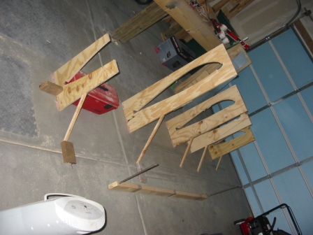
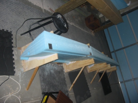
| 2/10/08
Preparing jigs on the garage floor. These are for the left side. |
 |
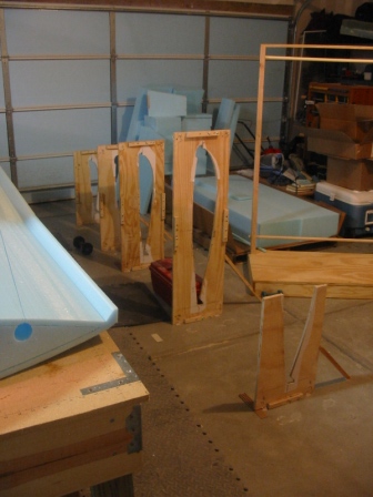
| 3/14/08
Jigs for right wing. |
 |
| Step 3: Cutting foam cores | |
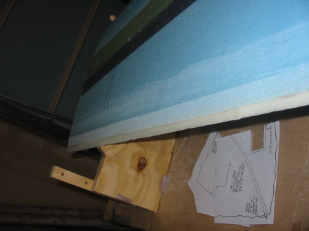
| 2/10/08
I had to get a scroll saw to get the cuts right. This is .025" thick steel with the templates glued on top. |
 |
| 2/10/08
Ditto. |
 |
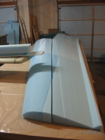
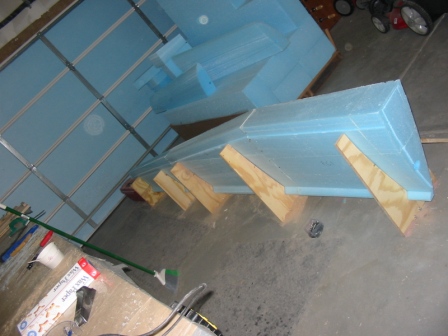
| 2/21/08
Left side. All cuts are done and the pieces are laid out on the table. |
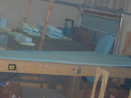 |
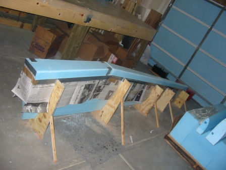
| 2/21/08
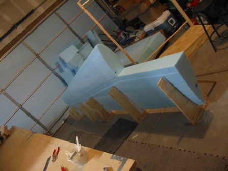
Left side. Long view. It looks like a wing! |
 |
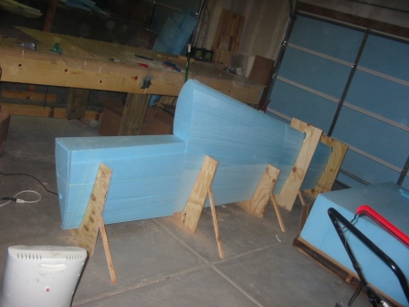
| 2/22/08
Left side. Bottom pieces are in the jigs and glued together, and held together with nails to dry. |
 |
| 2/22/08
Left side. Put the top pieces in place and attached front pieces of jigs to hold steady while everything cures. At the point the front two pieces of the wing are not glued, there's just there to hold things steady in the jigs. |
 |
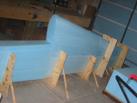
| 2/22/08
Left side. Another view. |
 |
| 3/16/08
Right side. Foam for right wing is cut and bonded into 5 pieces. |
 |
| 3/16/08
Right side. Right wing in the jigs. |
 |
| 3/18/08
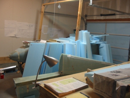
Foam carnage from cutting out the wings! There's an airplane in there somewhere. |
 |
| 3/16/08
Right side. We had some pretty bad lag cutting FC5, which necessitated removing the LE and cutting again with scraps. Here's the damaged LE after being removed from FC5. |
 |
| 3/16/08
Right side. Repairing the LE of FC5. Various scraps are micro'd in place and tacked with nails. This will all be sanded in later. |
 |
| Step 4: Assembly of foam cores and lay up of shear web | |
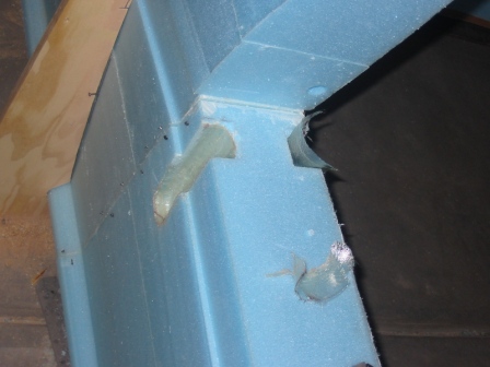
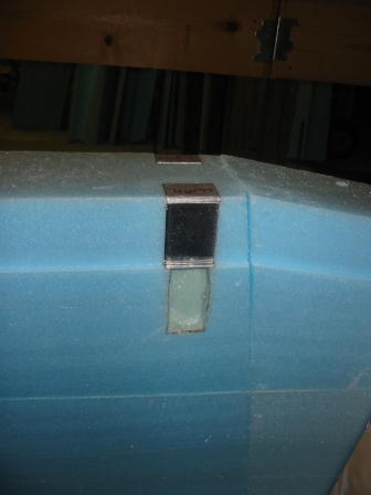
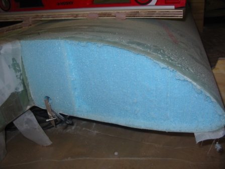
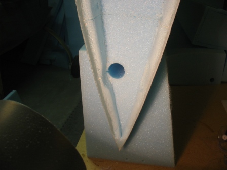
| 2/22/08
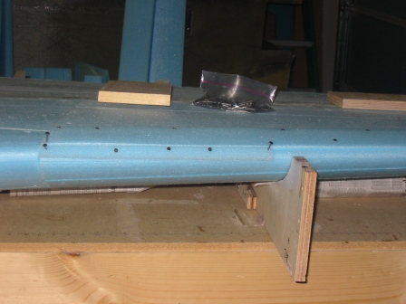
Left side. These depressions will be used to access the wing attach bolts. |
 |
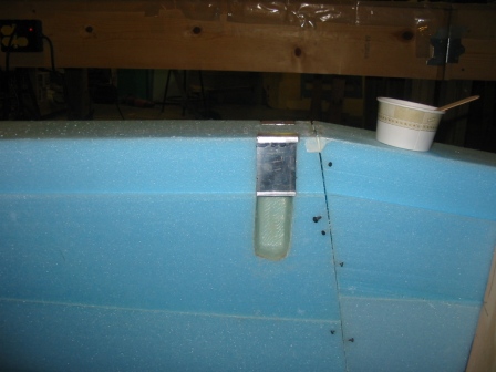
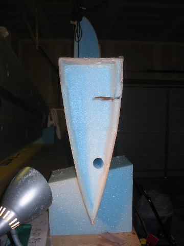
| 2/23/08
Left side. W18 cut to fit and 5ME'd in place over the depression and under LWA4. |
 |
| 2/23/08
Left side. Everything's ready for the shear web layup. |
 |
| 2/23/08
Left side. Done with the shear web layup, holding in place to cure. Now the front two pieces are glued in place, and the wing is a single piece. |
 |
| 3/17/08
Right side. LWA4 and W18 installed over attach depressions on right wing. |
 |
| 3/17/08
Right side. Preparing for the shear web layup on the right wing. |
 |
| Step 5: Bottom spar cap | |
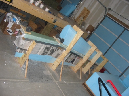
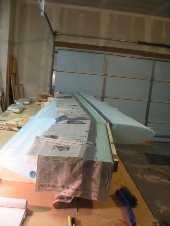
| 2/27/08
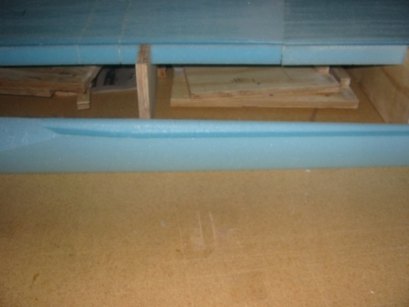
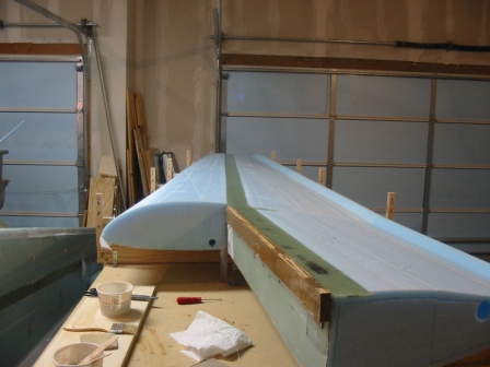
Left side. The whole wing has been moved to the table for the next bit of work. Removed the bottom piece of the jigs to expose the wing bottom. |
 |
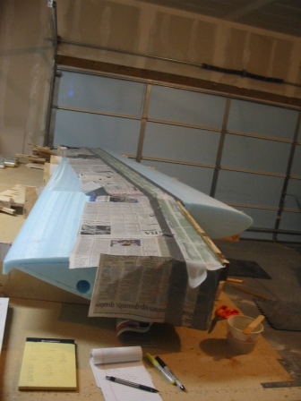
| 2/27/08
Left side. Everything's ready for the bottom spar cap layup. |
 |
| 2/27/08
Left side. Bottom spar cap layup is done. |
 |
| 3/18/08
Right side. Preparing for the bottom spar cap on the right wing. |
 |
| 3/18/08
Right side. Completed bottom spar cap on the right wing. |
 |
| Step 6: Bottom skin | |
| 3/2/08
Left side. Glass on the bottom. |
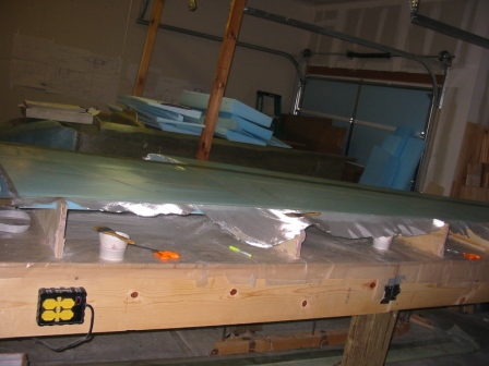 |
| 3/2/08
Left side. Dry micro in the TE channel. |
 |
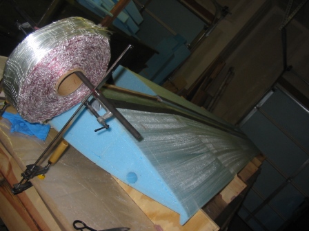
| 3/19/08
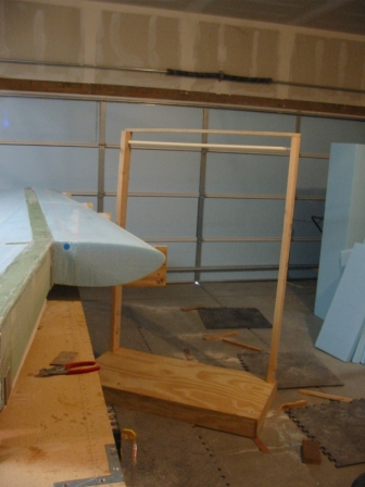
Right side. I built this stand to help with rolling out the cloth for the wings, since I would be doing the top and bottom skins on the right wing by myself. |
 |
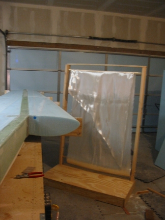
| 3/19/08
Right side. The UNI roll goes on a dowel near the bottom, and the cloth is pulled up over a bit of PVC pipe on a dowel. |
 |
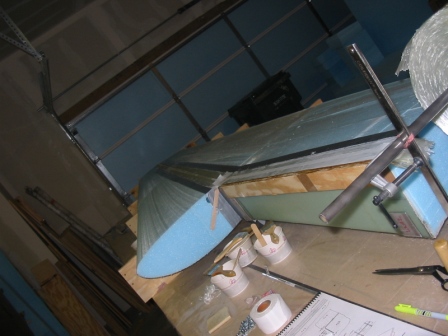
| 3/19/08
Right side. Like so. |
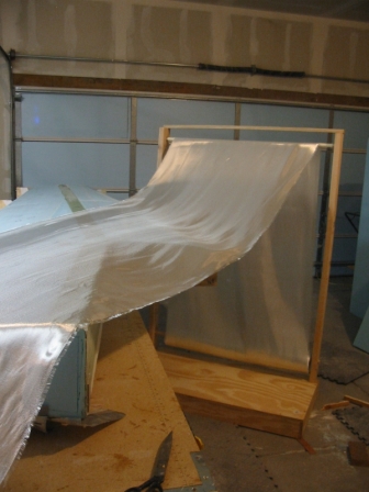 |
| 3/19/08
Right side. Really handy when you don't have a helper available! |
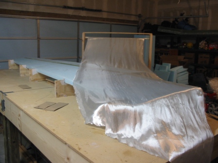 |
| 3/19/08
Right side. Skinning the bottom. |
 |
| 3/19/08
Right side. Bottom skin is done. |
 |
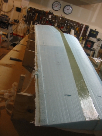
| Step 7: Top spar cap | |
| 3/5/08
Left side. Top spar cap is done. |
 |
| 3/20/08
Right side. Preparing for the top spar cap. |
 |
| 3/20/08
Right side. Top spar cap done. |
 |
| Step 8: Top skin | |
| 3/8/08
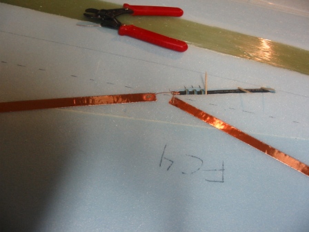
Left side. Positioning the coax for the FM radio attena. |
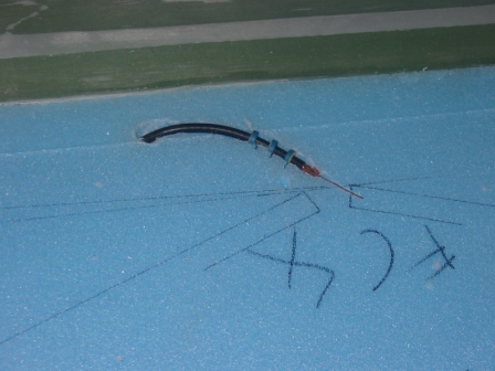 |
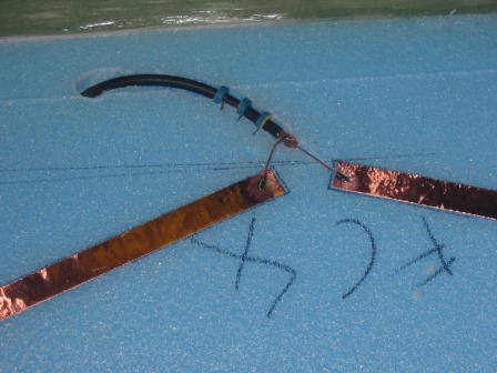
| 3/8/08
Left side. Completed the connections for the FM radio antenna. |
 |
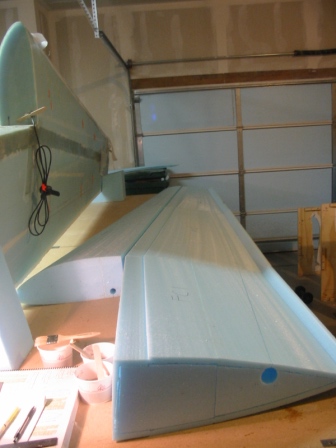
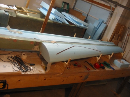
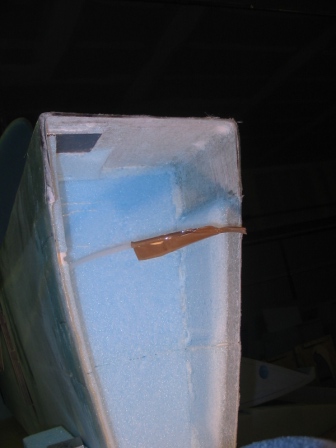
| 3/8/08
Left side. Antenna installed. To drill a hole for the coax down to the cable conduit, it wasn't a straight down hole; I had to drill at an angle. Here's how we did it. I pointed a laser pointer through the conduit and marked where the point hit the far wall. Then I pointed a laser level line so that it intersected the inboard hole, the mark on the wall, and then tilted it so it intersected the coax drill point on top of the wing. The laser line was now at an angle. I held the drill with the 12" long, 1/4" drill bit in alignment with this laser line, which pointed me directly at the conduit. Worked great! |
 |
| 3/8/08
Left side. Cut the fin off the tail before running the rudder cable conduit. |
 |
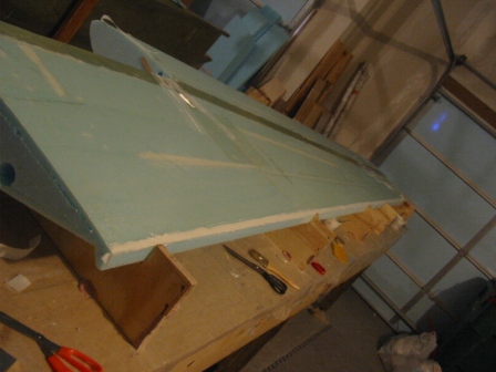
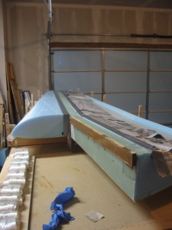
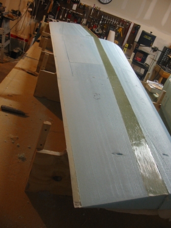
| 3/9/08
Left side. Glassing the top. |
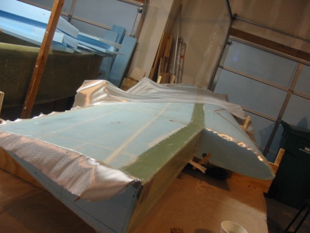 |
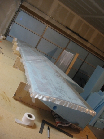
| 3/9/08
Left side. Top skin is done! |
 |
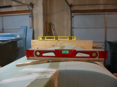
| 3/10/08
Left side. Level board bondo'd in place, top jig is level. |
 |
| 3/21/08
Right side. Pulling the peel ply off the TE of the right wing. This looks so terrible while you're doing it! |
 |
| 3/21/08
Right side. ...but it cleans up nice. |
 |
| 3/21/08
Right side. Drilled channel for rudder cable conduit. |
 |
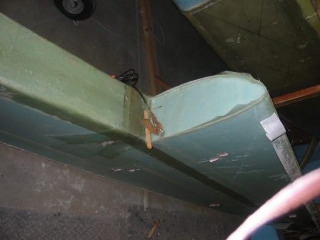
| 3/21/08
Right side. Installed rudder cable conduit, holding in place with toothpicks. |
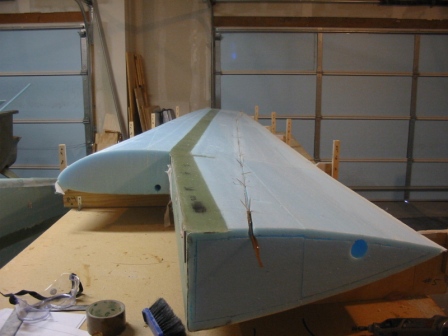 |
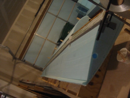
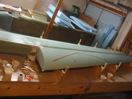
| 3/21/08
Right side. Installing a VHF-NAV antenna on top of right wing. |
 |
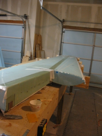
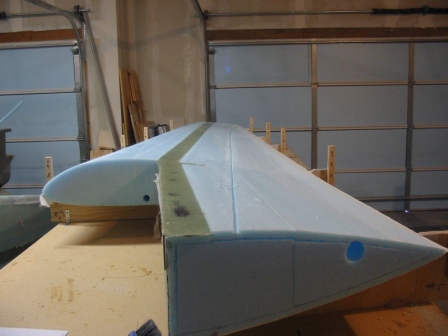
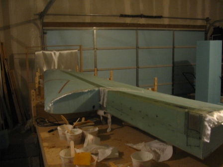
| 3/22/08
Right side. Top of right wing is done! |
 |
| Step 9: Wing ribs | |
| 3/11/08
Left side. Cutting 0.7" deep into forward rib. Used dremel with depth attachmnet. |
 |
| 3/11/08
Left side. Layups inside the rib. |
 |
| 3/11/08
Left side. Aft rib with foam removed for skin-skin bonding. |
 |
| 3/11/08
Left side. Depressions around torque tube. |
 |
| 3/27/08 Right side. Carved foam out from aft rib. |
 |
| Step 10: Ailerons | |
| Step 11: Controls | |
| Step 12: Attachment, wing to center spar |